International CME for Today's Radiologist
Global Radiology CME
Search Results
256 results found with an empty search
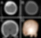
- Bifrontal Epidural Hematoma
29F with trauma and headache • Xray of the Week Figure 1. What is the important finding on this CT scan. Figure 2. A. Axial CT brain showing epidural hematoma in frontal region (yellow arrow). B. Axial CT brain showing fracture of right frontal bone (red arrow) C. Coronal CT brain showing right frontal epidural hematoma extending across the midline to the left frontal region (yellow arrows). D. 3D CT showing linear fracture of right frontal bone (red arrow) and left parietal bone (green arrow). Discussion: Epidural hematomas (EDH) refer to bleeding between the skull and the dura mater (1). EDH can occur when skull fractures result in arterial or venous injuries, causing pooling of blood in the epidural space (1). The majority of EDH's are unilateral and supratentorial, and 20% are frontal (2). Damage to a branch of the middle meningeal artery is the most common source of bleeding, but some EDH's can be attributed to venous bleeding after laceration of a dural venous sinus (3). Patients with EDH may initially lose consciousness and then regain consciousness and appear normal during a “lucid interval” before losing consciousness again (4). This lucid interval is an important characteristic of EDH that may help in diagnosis. On CT scan, EDH's present as a hyperdense, biconvex-shaped mass. Whereas subdural hematomas are not limited by the sutures, EDH's usually do not cross suture lines since blood cannot expand beyond the point where the dura attaches to the cranial sutures (1). However, the EDH in this case is unique because it does cross the sagittal suture. This can occur when diastatic fractures cause widening of sutures, allowing blood to cross the suture lines (3,10). In this case, the fracture crosses the sagittal suture (Fig. 2D) with resultant acute bifrontal EDH. Larger EDH's can also present with midline shift or compression of the ventricles due to mass effect (3). In acute bleeding, the non-clotted fresh blood appears as areas of low density on CT, also known as a swirl sign (5). Subacute EDH occurs between days 2-4 and appears solid while chronic EDH occurs between days 7-20 and appears as mixed or lucent with contrast enhancement (3). MRI can also be used to visualize EDH as it is more sensitive than CT. The presence of the displaced dura as a hypointense line on T1 and T2 on MRI is a key finding in EDH (6). MRI can also be used to differentiate between acute and chronic EDH. Acute EDH appears isointense on T1 with varying intensities on T2 while chronic EDH appears hyperintense on T1 and T2 (6). Angiography of EDH can show tears of the middle meningeal artery. In rare cases, EDH can appear with a “tram track sign” on angiography due to extravasation of contrast into the paired meningeal veins (7, 8). Treatment for acute and symptomatic EDH is hematoma evacuation to reduce pressure on the brain (9). Burr hole evacuation can also be used, and craniotomy may be necessary in large hematomas (3, 9). Non-surgical treatment is rare, but can be appropriate if there is a midline shift less than 5 mm, an EDH volume less than 30 ml, clot diameter less than 15 mm, and Glasgow Coma Score greater than 8 with no focal neurological symptoms (3). Follow up includes neurological examinations and surveillance with brain imaging to ensure that the hematoma does not expand (3, 9). References: 1. Heit JJ, Iv M, Wintermark M. Imaging of Intracranial Hemorrhage. J Stroke. 2017;19(1):11-27. doi:10.5853/jos.2016.00563 2. Bonfante, Eliana, and Roy Riascos. “Imaging of Brain Concussion.” Neuroimaging Clinics of North America, vol. 28, no. 1, Feb. 2018, p. i. doi:10.1016/S1052-5149(17)30140-5. 3. Khairat A, Waseem M. Epidural Hematoma. [Updated 2020 Jul 5]. In: StatPearls [Internet]. Treasure Island (FL): StatPearls Publishing; 2020 Jan-. Available from: https://www.ncbi.nlm.nih.gov/books/NBK518982/ 4. Ganz JC. The lucid interval associated with epidural bleeding: evolving understanding. J Neurosurg. 2013;118(4):739-745. doi:10.3171/2012.12.JNS121264 5. Gupta VK, Seth A. "Swirl Sign" in Extradural Hematoma. World Neurosurg. 2019;121:95-96. doi:10.1016/j.wneu.2018.10.010 6. Marincek BF, Dondelinger RF. Emergency Radiology: Imaging and Intervention. Berlin, Heidelberg: Springer-Verlag Berlin Heidelberg; 2007:109-110. doi:10.1007/978-3-540-68908-9 7. Yu J, Guo Y, Xu B, Xu K. Clinical importance of the middle meningeal artery: A review of the literature. Int J Med Sci. 2016;13(10):790-799. Published 2016 Oct 17. doi:10.7150/ijms.16489 8. Paiva WS, Andrade AF, Amorim RL, et al. Computed tomography angiography for detection of middle meningeal artery lesions associated with acute epidural hematomas. Biomed Res Int. 2014;2014:413916. doi:10.1155/2014/413916 9. Ren H, Yin L, Ma L, Wei M, Ma X. Emergency bedside evacuation of a subset of large postoperative epidural hematomas after neurosurgical procedures. Medicine (Baltimore). 2018;97(30):e11475. doi:10.1097/MD.0000000000011475 10. Huisman TA, Tschirch FT. Epidural hematoma in children: do cranial sutures act as a barrier?. J Neuroradiol. 2009;36(2):93-97. doi:10.1016/j.neurad.2008.06.003 Amara Ahmed is a medical student at the Florida State University College of Medicine. She serves on the executive board of the American Medical Women’s Association and Humanities and Medicine. She is also an editor of HEAL: Humanism Evolving through Arts and Literature, a creative arts journal at the medical school. Prior to attending medical school, she graduated summa cum laude from the Honors Medical Scholars program at Florida State University where she completed her undergraduate studies in exercise physiology, biology, and chemistry. In her free time, she enjoys reading, writing, and spending time with family and friends. Follow Amara Ahmed on Twitter @Amara_S98 All posts by Amara Ahmed Kevin M. Rice, MD is the president of Global Radiology CME Dr. Rice is a radiologist with Renaissance Imaging Medical Associates and is currently the Vice Chief of Staff at Valley Presbyterian Hospital in Los Angeles, California. Dr. Rice has made several media appearances as part of his ongoing commitment to public education. Dr. Rice's passion for state of the art radiology and teaching includes acting as a guest lecturer at UCLA. In 2015, Dr. Rice and Natalie Rice founded Global Radiology CME to provide innovative radiology education at exciting international destinations, with the world's foremost authorities in their field. In 2016, Dr. Rice was nominated and became a semifinalist for a "Minnie" Award for the Most Effective Radiology Educator. Follow Dr. Rice on Twitter @KevinRiceMD All posts by Kevin M. Rice, MD
- Traumatic Thoracic Aortic Injury
48 year old male with chest pain following a motor vehicle collision • Xray of the Week Figure 1. Name the important findings on this CXR and CT Scan. Figure 2. Imaging results of a trauma patient who was in a motor vehicle collision. A: Chest X-ray demonstrating a widening of the mediastinum (yellow arrows). B: Axial CT image of the chest showing subtle pseudoaneurysm along the lateral aspect of the aortic arch (red arrow). C: Coronal CT image of the chest showing hematoma adjacent to the site aortic injury (blue arrow). Figure 3. Same patient as in figure 2, one month after aortic stent graft. A: Chest X-ray showing a normal width of the mediastinum after the placement of the stent graft (yellow arrow). B & C: Axial and coronal CT images of the chest showing a good expansion of the stent without adjacent hematoma or leak (red and blue arrows). Figure 4. Traumatic Aortic Injury Grading System (5)- Diagram by Han Ngo Grade 1: Intimal flap/intimal tear. Grade 2: Intramural hematoma (hemorrhage without an intimal tear). Grade 3: Aortic pseudoaneurysm (false aortic rupture contained by the thin wall of adventitia). Grade 4: Aortic transection (true aortic rupture due to the damage of all three layers). Discussion: Thoracic aortic injury is the most common type of traumatic aortic injury (TAI), a life-threatening condition that frequently occurs as a result of crush or deceleration injuries. As the second most common cause of death in patients with blunt trauma, TAI has a very high mortality rate with up to 80% of patients die at the scene of trauma and of those who survive the arrival to the ER, 30% die within the first 24 hours (1). Early diagnosis of TAI relies on appropriate imaging since clinical symptoms and examination are nonspecific. Chest X-ray can detect indirect signs of TAI such as widened mediastinum (Figs. 1,2), trachea displacement, depression of left main bronchus, obliteration of aortic knob contour, left apical pleural cap, or hemothorax. Although nonspecific, these findings should raise high suspicion for TAI when present in blunt trauma cases. CT scan can reveal direct signs of TAI through the visualization of aortic injuries (Figs. 1,2). Aortic injuries are categorized into four grades based on severity: intimal flap, intramural hematoma, pseudoaneurysm, or aortic transection (2-5) (Fig. 4). This is a case of Grade 3 injury due to the presence of a pseudoaneurysm (Fig. 1,2). Aortic stent graft (Fig. 3) is the preferred treatment for TAI because of its higher success rate and lower rate of complication than open surgical repair. The stent is placed by inserting a catheter with the compressed stent through an artery, most commonly the femoral artery. Once the stent reaches the site of aortic lesion, it is expanded to form a new aortic wall and prevent more blood from entering the pseudoaneurysm (3-5). References: 1. Igiebor OS, Waseem M. Aortic Trauma. StatPearls Publishing LLC. https://www.ncbi.nlm.nih.gov/books/NBK459337/. Published December 16, 2019. Accessed June 30, 2020. 2. Yahia DAA, Bouvier A, Nedelcu C, et al. Imaging of thoracic aortic injury. Diagn Interv Imaging. 2015;96(1):79-88. doi:10.1016/j.diii.2014.02.003 3. Mokrane FZ, Revel-Mouroz P, Saint Lebes B, Rousseau H. Traumatic injuries of the thoracic aorta: The role of imaging in diagnosis and treatment. Diagn Interv Imaging. 2015;96(7-8):693-706. doi:10.1016/j.diii.2015.06.005 4. Yamane BH, Tefera G, Hoch JR, et al. Blunt thoracic aortic injury: Open or stent graft repair? Surgery. 2008;144(4):575-582. doi:10.1016/j.surg.2008.06.007 5. Azizzadeh A, Keyhani K, Miller CC, et al. Blunt traumatic aortic injury: Initial experience with endovascular repair. J Vasc Surg. 2009 Jun;49(6):1403-8. doi:10.1016/j.jvs.2009.02.234 Han Ngo is a medical student at Oakland University William Beaumont School of Medicine (OUWB) in Rochester, Michigan. She graduated from UCLA, receiving her B.S. degree in Biochemistry. Prior to starting medical school, Han spent 4+ years (including her undergraduate years) working as a medical scribe for a psychiatrist at Ronald Reagan UCLA Medical Center. Interested in radiology, Han is now serving as the President of both diagnostic radiology and interventional radiology interest groups at OUWB. She is also a committee member on the Medical Student Council of the Society of Interventional Radiology (SIR). After deciding on her specialty, Han plans to continue learning and striving to make a difference in patients’ lives. Follow Han Ngo on Twitter @Han_Ngoo All posts by Han Ngo Kevin M. Rice, MD is the president of Global Radiology CME Dr. Rice is a radiologist with Renaissance Imaging Medical Associates and is currently the Vice Chief of Staff at Valley Presbyterian Hospital in Los Angeles, California. Dr. Rice has made several media appearances as part of his ongoing commitment to public education. Dr. Rice's passion for state of the art radiology and teaching includes acting as a guest lecturer at UCLA. In 2015, Dr. Rice and Natalie Rice founded Global Radiology CME to provide innovative radiology education at exciting international destinations, with the world's foremost authorities in their field. In 2016, Dr. Rice was nominated and became a semifinalist for a "Minnie" Award for the Most Effective Radiology Educator. Follow Dr. Rice on Twitter @KevinRiceMD All posts by Kevin M. Rice, MD
- Tibialis Anterior Tendon Tear
Forced plantar flexion on an extended foot. Anterior ankle pain and weakness • Xray of the Week What is the diagnosis? Figure 1. What is the important finding on this MRI of the ankle. Figure 2. A: T1 weighted axial image with tibialis anterior rupture (yellow arrow). B: T1 weighted sagittal image with tibialis anterior tendon discontinuity, retraction and soft tissue edema (yellow arrow). C: T2 weighted axial image with tibialis anterior rupture (yellow arrow). D: T2 weighted sagittal image with tibialis anterior tendon discontinuity, retraction, and soft tissue edema (yellow arrow). Discussion: Anterior ankle tendinopathy can involve the tibialis anterior, extensor digitorum longus, or extensor hallucis longus. Anatomically, the anterior tibialis muscle tendon inserts at the plantar and medial aspect of the first metatarsal and cuneiform bones (4). The tibialis anterior muscle is the main dorsiflexor for the foot. Since the tendon is under the retinaculum, mechanical demand is less compared to the other tendons, leading to less irritation and tearing (4). Rupture of the tibialis anterior tendon can occur due a sudden force typically in the opposite direction of tendon function: forced plantar flexion of an extended foot. Rupture can also occur with degenerative processes typically affecting the distal avascular portion of the tendon (1). These degeneration etiologies can include impingement, inflammatory arthritis, diabetes mellitus, or chronic microtrauma leading to tendinosis (4). Upon tendon rupture, patients may present with anterior ankle pain and weakness. In addition, there may be a painless mass on the anteromedial aspect of the ankle due to the ruptured tendon and adjacent inflammation. Patients can have delayed presentation due to the compensation of the extensor hallucis longus and extensor digitorum muscles (1,3). This injury typically presents more in an older population due to the decreased tendon elasticity (2). In this case, the patient presented due to forced plantar flexion on an extended foot leading to a retracted full thickness tear. Imaging can prove helpful in making the diagnosis of tendon rupture, especially when the clinical and physical findings are vague. When evaluating an MR image of the ankle, normal tendons have low signal intensity on all sequences (4). With complete anterior tibial tendon rupture, discontinuity and retraction of the proximal tendon segment is apparent (4). Figures 2B and 2D demonstrate discontinuity, with rupture of the tendon and adjacent soft tissue swelling. In the setting of a tendon rupture, the tibialis anterior tendon is visualized on the medial side of the ankle with surrounding edema denoted by the yellow arrow on Figures 2A and 2C. Common sequelae of tendon rupture include foot drop, flatfoot, and compromised gait (3). Initial treatment includes conservative methods such as casting or orthotics. Surgery with direct repair or reconstruction may be indicated in athletes or after failure of conservative management (3). References: Waizy H, Bouillon B, Stukenborg-Colsman C, et al. Ruptur der Musculus-tibialis-anterior-Sehne : Ätiologie, klinische Symptome und Therapie [Rupture of the tendon of the tibialis anterior muscle : Etiology, clinical symptoms and treatment]. Unfallchirurg. 2017;120(12):1015-1019. doi:10.1007/s00113-017-0417-z Kausch T, Rütt J. Subcutaneous rupture of the tibialis anterior tendon: review of the literature and a case report. Arch Orthop Trauma Surg. 1998;117(4-5):290-293. doi:10.1007/s004020050250 Christman-Skieller C, Merz MK, Tansey JP. A systematic review of tibialis anterior tendon rupture treatments and outcomes. Am J Orthop (Belle Mead NJ). 2015;44(4):E94-E99. https://pubmed.ncbi.nlm.nih.gov/25844597/ Khoury NJ, el-Khoury GY, Saltzman CL, Brandser EA. Rupture of the anterior tibial tendon: diagnosis by MR imaging. AJR Am J Roentgenol. 1996;167(2):351-354. doi:10.2214/ajr.167.2.8686602 Amer Ahmed is a fourth-year medical student at Midwestern University Chicago College of Osteopathic Medicine. There, he has served as the President for the Medical Business Association and Secretary for the Radiology Interest Group. Before medical school, Amer earned a degree in Economics at Loyola University Chicago and spent some time as an Investment Specialist at Merrill Edge before deciding to pursue his interest in medicine. Radiology intrigued Amer following a back injury requiring him to get an MRI. That is when he was able to appreciate the eye for detail Radiologists possess. Amer is passionate about finance, medicine, and technology. Follow Amer Ahmed on Twitter @amer_ahmed401 All posts by Amer Ahmed Phillip Tirman, MD is the Medical Director of Musculoskeletal Imaging at the Renaissance Imaging Center in Westlake Village, California. A nationally recognized expert in the applications of MRI for evaluating MSK and spine disorders, Dr. Tirman is the co-author of three textbooks, including MRI of the Shoulder and Diagnostic Imaging: Orthopedics. He is also the author or co-author of over sixty original scientific articles published in the radiology and orthopedic literature. All posts by Phillip Tirman Kevin M. Rice, MD is the president of Global Radiology CME Dr. Rice is a radiologist with Renaissance Imaging Medical Associates and is currently the Vice Chief of Staff at Valley Presbyterian Hospital in Los Angeles, California. Dr. Rice has made several media appearances as part of his ongoing commitment to public education. Dr. Rice's passion for state of the art radiology and teaching includes acting as a guest lecturer at UCLA. In 2015, Dr. Rice and Natalie Rice founded Global Radiology CME to provide innovative radiology education at exciting international destinations, with the world's foremost authorities in their field. In 2016, Dr. Rice was nominated and became a semifinalist for a "Minnie" Award for the Most Effective Radiology Educator. Follow Dr. Rice on Twitter @KevinRiceMD All posts by Kevin M. Rice, MD
- Smith Fracture
28 yo male with wrist pain due to a fall • Xray of the Week What is the eponymous name of this fracture? Figure 1: Type 1 Smith fracture: Volar displacement of distal fragment of radius fracture (blue arrow). Note that this is an extraarticular fracture. Figure 2: Type 2 Smith fracture in a different patient: Volar and proximal displacement of distal fragment of radius fracture (blue arrow). Note that this is an intraarticular fracture (yellow arrow). Figure 3: Mechanism of injury for Smith fracture. Diagram by Shama Jaswal. Discussion: A Smith fracture or a reverse Colles fracture is an extraarticular fracture of the distal radius with a volar displacement or angulation of the distal fragment (Figs. 1,2). It was named by Irish surgeon Robert William Smith in 1847, who incidentally followed Abraham Colles as Professor of Surgery at Trinity College in Dublin [1]. Smith fractures are rare, making up approximately 5% of all radial and ulnar fractures combined. It commonly occurs either after a fall onto a flexed wrist or as a direct blow to the dorsal aspect of the wrist (Fig. 3). One of the diagnostic criteria includes deformed wrist with swelling visible on the volar side and the prominence of the ulna along the dorsum of the wrist [1]. Up to 15% of these fractures may show symptoms related to compression of the median and/or ulnar nerve; therefore, neurovascular evaluation is imperative [2,3]. Standard wrist radiographs are usually adequate to differentiate between Colles and Smith fractures. (Figs. 1,2) [4]. When there is extensive comminution or intra-articular fracture, CT helps define the injury and assist with surgical planning. Disruption of the distal radioulnar joint (DRUJ) and the triangular fibrocartilage complex (TFCC) are often seen along with other soft tissue injuries which are well assessed with MRI [5]. Smith fracture is divided into three types: [6] • Type I - most common type, accounting for about 85% of cases, is an extraarticular fracture through the distal radius (Fig. 1) • Type II - less common, accounting for approximately 13%, is an intraarticular oblique fracture, also referred to as a reverse Barton fracture (Fig. 2) • Type III - uncommon, less than 2%, is a juxta-articular oblique fracture The mainstay of treatment of non-displaced and stable distal radius fractures is closed reduction and immobilization [6]. Closed reduction using percutaneous pinning with K-wires can be performed in patients with good bone quality and minimal comminution [6,7]. For an unstable or irreducible fracture, ORIF with a volar plate is required [8-11]. Complications include malunion and compression of the median nerve causing carpal tunnel syndrome [12]. Entrapment of the extensor pollicis longus (EPL) tendon with malunion is seen in both conservative and ORIF surgeries [13-15]. Late rupture of the EPL has been demonstrated previously [16, 17]. Similarly development of complex regional pain syndrome (CRPS) has been reported in up to nearly 40% of fractures [18]. References: 1. Shah, H.M. and K.C. Chung, Robert William Smith: his life and his contributions to medicine. J Hand Surg Am, 2008. 33(6): p. 948-51 DOI: 10.1016/j.jhsa.2007.12.020 2. Ford, D.J. and M.S. Ali, Acute carpal tunnel syndrome. Complications of delayed decompression. J Bone Joint Surg Br, 1986. 68(5): p. 758-9. 3. McKay, S.D., et al., Assessment of complications of distal radius fractures and development of a complication checklist. J Hand Surg Am, 2001. 26(5): p. 916-22 DOI: 10.1053/jhsu.2001.26662 4. Dóczi, J., et al., Occult distal radial fractures. J Hand Surg Br, 1995. 20(5): p. 614-7 DOI: 10.1016/s0266-7681(05)80121-4 5. Mills, T.J., Smith's fracture and anterior marginal fracture of radius. Br Med J, 1957. 2(5045): p. 603-5 DOI: 10.1136/bmj.2.5045.603 6. Schroeder, J.D. and M. Varacallo, Smith's Fracture Review, in StatPearls. 2020, StatPearls Publishing Copyright © 2020, StatPearls Publishing LLC.: Treasure Island (FL). 7. Glickel, S.Z., et al., Long-term outcomes of closed reduction and percutaneous pinning for the treatment of distal radius fractures. J Hand Surg Am, 2008. 33(10): p. 1700-5 DOI: 10.1016/j.jhsa.2008.08.002 8. Downing, N.D. and A. Karantana, A revolution in the management of fractures of the distal radius? J Bone Joint Surg Br, 2008. 90(10): p. 1271-5 DOI: 10.1302/0301-620x.90b10.21293 9. Orbay, J.L. and A. Touhami, Current concepts in volar fixed-angle fixation of unstable distal radius fractures. Clin Orthop Relat Res, 2006. 445: p. 58-67 PubMed: https://pubmed.ncbi.nlm.nih.gov/16505728/ DOI:10.1097/01.blo.0000205891.96575.0f 10. Schneppendahl, J., J. Windolf, and R.A. Kaufmann, Distal radius fractures: current concepts. J Hand Surg Am, 2012. 37(8): p. 1718-25 DOI: 10.1016/j.jhsa.2012.06.001 11. Tang, J.B., Distal radius fracture: diagnosis, treatment, and controversies. Clin Plast Surg, 2014. 41(3): p. 481-99 DOI: 10.1016/j.cps.2014.04.001 12. Mackinnon, S.E., Pathophysiology of nerve compression. Hand Clin, 2002. 18(2): p. 231-41 DOI: 10.1016/s0749-0712(01)00012-9 13. Franz, T., Entrapment of Extensor Pollicis Longus Tendon after Volar Plating of a Smith Type Pediatric Distal Forearm Fracture. J Hand Surg Asian Pac Vol, 2016. 21(2): p. 253-6 DOI: 10.1142/s2424835516720085 14. Mansour, A.A., 3rd, J.T. Watson, and J.E. Martus, Displaced dorsal metaphyseal cortex associated with delayed extensor pollicis longus tendon entrapment in a pediatric Smith's fracture. J Surg Orthop Adv, 2013. 22(2): p. 173-5 DOI: 10.3113/jsoa.2013.0173 15. Murakami, Y. and K. Todani, Traumatic entrapment of the extensor pollicis longus tendon in Smith's fracture of the radius-case report. J Hand Surg Am, 1981. 6(3): p. 238-40 DOI: 10.1016/s0363-5023(81)80076-7 16. Bonatz, E., T.D. Kramer, and V.R. Masear, Rupture of the extensor pollicis longus tendon. Am J Orthop (Belle Mead NJ), 1996. 25(2): p. 118-22. 17. Roth, K.M., et al., Incidence of extensor pollicis longus tendon rupture after nondisplaced distal radius fractures. J Hand Surg Am, 2012. 37(5): p. 942-7 DOI: 10.1016/j.jhsa.2012.02.006 18. Li, Z., et al., Complex regional pain syndrome after hand surgery. Hand Clin, 2010. 26(2): p. 281-9 DOI: 10.1016/j.hcl.2009.11.001 Shama Jaswal is an International Medical Graduate, currently doing research at Mallinckrodt Institute of Radiology (MIR), Saint Louis. She aims at pursuing Diagnostic Radiology residency and poses a keen interest in research alongside academics. At MIR, she has been fortunate to work on various oncology projects including the project in which they studied how the difference in fat metabolism in both sexes can affect the cancer survival and outcome, and how this study can further improve prognosis through treatment modification. Shama is both an accomplished sprinter and singer having won several national competitions in in each discipline in India. She also has a strong passion for cooking and gardening. Follow Shama Jaswal on Twitter @Jaswal_Shama All posts by Shama Jaswal Kevin M. Rice, MD is the president of Global Radiology CME Dr. Rice is a radiologist with Renaissance Imaging Medical Associates and is currently the Vice Chief of Staff at Valley Presbyterian Hospital in Los Angeles, California. Dr. Rice has made several media appearances as part of his ongoing commitment to public education. Dr. Rice's passion for state of the art radiology and teaching includes acting as a guest lecturer at UCLA. In 2015, Dr. Rice and Natalie Rice founded Global Radiology CME to provide innovative radiology education at exciting international destinations, with the world's foremost authorities in their field. In 2016, Dr. Rice was nominated and became a semifinalist for a "Minnie" Award for the Most Effective Radiology Educator. Follow Dr. Rice on Twitter @KevinRiceMD All posts by Kevin M. Rice, MD
- Lunate Dislocation
Trauma. Wrist pain. • Xray of the Week Figure 1. What is the diagnosis? Figure 2. A. PA radiograph of lunate dislocation with triangular, “piece of pie” lunate appearance (green arrows), disruption of carpal arcs, increased radiolunate space, and overlap of lunate with other carpals. B. Lateral radiograph showing the “spilled teacup” appearance of lunate dislocation (yellow arrows), with the concavity of the lunate facing anteriorly. The lunate has volar displacement and angulation, and has lost articulation with the radius and capitate. Discussion: Lunate dislocations are typically a consequence of traumatic forces causing wrist hyperextension, such as a fall on an outstretched hand (1,2). Mayfield and colleagues described a progression of perilunate dislocation, with complete lunate dislocation representing the final stage of ligamentous and osseous failure with the greatest degree of carpal instability (Fig. 3) (2,3). Herzberg et al. further classified lunate dislocation according to volar displacement and rotation, with degree of rotation corresponding to increased probability of soft-tissue interposition and decreased likelihood of successful closed reduction (1,4). Patients may present with wrist swelling and pain, reduced range of motion, and symptoms of median nerve impingement (2). Figure 3. Mayfield Classification of Carpal Dislocations. from https://wikem.org/wiki/Perilunate_and_lunate_dislocations On plain radiographs, the PA view is useful for evaluating Gilula’s carpal arcs, three contours normally formed by the proximal and distal carpal rows that are interrupted by lunate dislocation (2,5). Figures 1A and 2A demonstrate this finding, along with overlapping of the lunate with the capitate, increased radiolunate distance, loss of total carpal height, and triangular “piece of pie” lunate appearance (1,2,5). The lateral radiograph is useful for detecting palmar dislocation and rotation of the lunate. Figures 1B and 2B show volar dislocation of the lunate from the lunate fossa, volar angulation of the lunate, loss of articulation and alignment with the radius and capitate, an abnormal scapho-lunate angle, and a “spilled teacup” appearance (1,2,5). The lateral view can also distinguish lunate dislocation from perilunate dislocation, in which the lunate remains articulated with the radius and the remainder of the carpal bones are displaced dorsally (1,2). Evaluation of wrist pathology can also be aided by CT, US, or fluoroscopy when radiographs are indeterminate (1,6). Diagnosis of lunate and perilunate dislocation following wrist trauma is missed in up to 25% of cases, and reduction and ligament repair are necessary to prevent joint dysfunction (4). Late presentation can lead to avascular necrosis (2). Even with early treatment, however, over 50% of patients in a multi-center study experienced post-traumatic arthritis (4). Other complications include wrist pain and stiffness, median nerve injury, tendon rupture, and carpal instability (1,2,5). Closed reduction was previously the recommended treatment and is employed in the acute setting, though open reduction with fixation and ligament repair is now preferred (1,2). References: 1. Scalcione LR, Gimber LH, Ho AM, Johnston SS, Sheppard JE, Taljanovic MS. Spectrum of carpal dislocations and fracture-dislocations: imaging and management. AJR Am J Roentgenol. 2014;203(3):541-550. doi:10.2214/AJR.13.11680 2. Grabow RJ, Catalano L 3rd. Carpal dislocations. Hand Clin. 2006;22(4):485-vii. doi:10.1016/j.hcl.2006.07.004 3. Mayfield JK, Johnson RP, Kilcoyne RK. Carpal dislocations: pathomechanics and progressive perilunar instability. J Hand Surg Am. 1980;5(3):226-241. doi:10.1016/s0363-5023(80)80007-4 4. Herzberg G, Comtet JJ, Linscheid RL, Amadio PC, Cooney WP, Stalder J. Perilunate dislocations and fracture-dislocations: a multicenter study. J Hand Surg Am. 1993;18(5):768-779. doi:10.1016/0363-5023(93)90041-Z 5. Tucker A, Marley W, Ruiz A. Radiological signs of a true lunate dislocation. BMJ Case Rep. 2013;2013:bcr2013009446. Published 2013 Apr 23. doi:10.1136/bcr-2013-009446 6. Kim K, Kim MW. Ultrasonography Detected Missed Lunate Volar Dislocation Associated With Median Neuropathy: A Case Report. Ann Rehabil Med. 2017;41(4):709-714. doi:10.5535/arm.2017.41.4.709 Ian Rumball is a medical student and aspiring radiologist at the Zucker School of Medicine at Hofstra/Northwell in Hempstead, NY. He serves as chair for his school’s radiology interest group. Prior to medical school, he attended the University of Wisconsin - Madison and graduated with degrees in biology, history, global health, and African studies. As an undergraduate, he did research in the fields of oncology, hematology, and neuroendocrinology. He also published work in undergraduate journals of creative writing, history, and physiology. In his free time, Ian enjoys playing guitar, hiking his local state parks, and watching classic films. Follow Ian Rumball on Twitter @RumballIan All posts by Ian Rumball Kevin M. Rice, MD is the president of Global Radiology CME Dr. Rice is a radiologist with Renaissance Imaging Medical Associates and is currently the Vice Chief of Staff at Valley Presbyterian Hospital in Los Angeles, California. Dr. Rice has made several media appearances as part of his ongoing commitment to public education. Dr. Rice's passion for state of the art radiology and teaching includes acting as a guest lecturer at UCLA. In 2015, Dr. Rice and Natalie Rice founded Global Radiology CME to provide innovative radiology education at exciting international destinations, with the world's foremost authorities in their field. In 2016, Dr. Rice was nominated and became a semifinalist for a "Minnie" Award for the Most Effective Radiology Educator. Follow Dr. Rice on Twitter @KevinRiceMD All posts by Kevin M. Rice, MD
- Sandblasting Injury of Hand
What is the mechanism of injury? • Xray of the Week Figure 1. Frontal and lateral plain radiographs of the left hand and lateral plain radiograph of the left forearm. Figure 2. Frontal and lateral plain radiographs of the left hand and lateral plain radiograph of the left forearm demonstrating occupational sandblasting injury. A. Frontal x-ray of left hand showing radiopaque sand (red arrows) in the 1st metacarpal web space and extensive subcutaneous emphysema throughout the hand (yellow arrows). B. Lateral x-ray of left hand demonstrating radiopaque sand (red arrows) in the 1st metacarpal web space and around the adjacent proximal 1st phalanx. C. Lateral x-ray of left forearm showing subcutaneous emphysema (yellow arrows) extending along the anterior surface of forearm. Discussion: Sandblasting is a form of abrasive blasting that involves the propulsion of sand particles at high speeds to clean, smooth, or shape various industrial surfaces. Sandblasting injuries are classified as high-pressure injection injuries and can result in significant trauma that may require emergent surgery (1,2). Although there is widespread usage of these high-pressure tools, high-pressure injection hand injuries are rarely seen and account only for a small number of total hand trauma cases (1-3). In cases of limited exposure and small injection sites, the overlying soft tissue may look grossly intact, but the underlying tissue is where extensive damage can occur including tissue ischemia, chemical irritation, muscle destruction, compression effects, and widespread edema (3). Rarely, subcutaneous emphysema can occur due to communication with surrounding atmospheric air, injection of air from the high-pressure device, and creation of a one-way valve system (4). The specific imaging features of sandblasting injuries and foreign bodies in general ultimately is determined by the composition of the material. Plain radiography is usually the first step in imaging hand trauma with suspected foreign body as it allows for potential classification of the material and location relative to other structures. Materials such as metal, glass, and stone, including sand, are readily picked up on plain radiographs and will appear radiopaque (Figs. 1,2) (5). Of note, wood and acrylic-based materials exhibit the opposite and will appear radiolucent on x-ray making the visualization of these materials difficult (5). Subcutaneous emphysema can be further visualized on conventional radiographs due to its lower density compared to surrounding soft tissues and bone (Figs. 1,2). CT can provide higher resolution and a precise measurement of the foreign body’s size and shape, although cross sectional imaging is rarely sought after in most cases (5,6). When concerning radiolucent materials, CT has greater utility in their detection when compared to conventional radiographs (5). Both CT and MRI can be utilized when surgery is in question and for assessing soft tissue, muscular, ligamentous, and tendinous damage (5,6). Sonographic features of most foreign bodies including stone will appear hyperechoic, but any air introduced to the surveyed area will lead to difficulty visualizing the foreign body (5). Treatment of these high-pressure injection injuries involves prompt evaluation of the wound and emergent surgical debridement to ensure the patient maintains function of the affected area and to reduce the need for amputation (5,6). References: Amir A, Sagi A, Barr J, Rosenberg L. 'Sand-blaster' injuries. Injury. 1996;27(3):223-224. doi:10.1016/0020-1383(95)00206-5 Belsole RJ, Nolan M, Eichberg RD. Sandblasting injury of the hand. J Hand Surg Am. 1982;7(5):523-525. doi:10.1016/s0363-5023(82)80054-3 Verhoeven N, Hierner R. High-pressure injection injury of the hand: an often underestimated trauma: case report with study of the literature. Strategies Trauma Limb Reconstr. 2008;3(1):27-33. doi:10.1007/s11751-008-0029-9. PubMed Full Text: https://www.ncbi.nlm.nih.gov/pmc/articles/PMC2291478/ Fox A, Sheick H, Ekwobi C, Ho-Asjoe M. Benign surgical emphysema of the hand and upper limb: gas is not always gangrene--a report of two cases. Emerg Med J. 2007;24(11):798-799. doi:10.1136/emj.2007.046755 PubMed Full Text: https://www.ncbi.nlm.nih.gov/pmc/articles/PMC2658337/ Aras MH, Miloglu O, Barutcugil C, Kantarci M, Ozcan E, Harorli A. Comparison of the sensitivity for detecting foreign bodies among conventional plain radiography, computed tomography and ultrasonography. Dentomaxillofac Radiol. 2010;39(2):72-78. doi:10.1259/dmfr/68589458 Collins M, McGauvran A, Elhassan B. High-pressure injection injury of the hand: peculiar MRI features and treatment implications. Skeletal Radiol. 2019;48(2):295-299. doi:10.1007/s00256-018-3005-6 Corey Stump is a medical student and aspiring radiologist at the Marian University College of Osteopathic Medicine in Indianapolis, Indiana. Prior to medical school, he graduated summa cum laude from Wittenberg University where he received a B.S. degree in Biology. He is excited to pursue a career in Diagnostic Radiology with interests in medical education. He has produced a webinar titled “Navigating The Virtual Match; Program Directors vs. Medical Students” through the Academy of Online Radiology Education with other medical students and radiologists around the country in an effort to provide insight on the 2020 residency match. He is passionate about teaching and he hopes to provide a meaningful experience to medical students one day. Follow Corey Stump on Twitter @corey_stump All posts by Corey Stump Kevin M. Rice, MD is the president of Global Radiology CME Dr. Rice is a radiologist with Renaissance Imaging Medical Associates and is currently the Vice Chief of Staff at Valley Presbyterian Hospital in Los Angeles, California. Dr. Rice has made several media appearances as part of his ongoing commitment to public education. Dr. Rice's passion for state of the art radiology and teaching includes acting as a guest lecturer at UCLA. In 2015, Dr. Rice and Natalie Rice founded Global Radiology CME to provide innovative radiology education at exciting international destinations, with the world's foremost authorities in their field. In 2016, Dr. Rice was nominated and became a semifinalist for a "Minnie" Award for the Most Effective Radiology Educator. Follow Dr. Rice on Twitter @KevinRiceMD All posts by Kevin M. Rice, MD
- Lung Herniation
56M with new chest mass after recent cardiac surgery • Xray of the Week 56 yo M with complaints of new chest mass, cough and chest pain. Patient recently had a minimally invasive secundum ASD and PFO closure. Patient noticed a mass bulging on his right side at the surgical site when coughing. What is the diagnosis? Figure 1. Patient with history of recent cardiac surgery presents with palpable right chest mass. What is the diagnosis? Figure 2. CT chest with contrast axial image shows a portion of the anterior basal segment right lower lobe herniating between two anterior ribs. Also noted is a large right hemothorax. Figure 3. CT chest oblique coronal image (A) with a volume rendered oblique coronal reconstruction image (B) again shows a portion of the anterior basal segment right lower lobe herniating between two anterior ribs. Figure 4. CT chest without contrast axial image after thoracotomy, lung herniation repair with pneumolysis of the anterior basal segment of the right lower lobe and drainage of a previous hemothorax with a chest tube (orange arrow). Discussion: Lung herniation occurs uncommonly, with 20% due to a congenital anomaly, and the remaining 80% acquired. Causes of acquired lung herniation include infection, neoplasm, trauma, and (as seen in this case) from recent or remote thoracic surgery [1]. Lung herniation most commonly occurs in the anterior region especially in the lower intercostal spaces due to less muscular support (Figs. 1-3) [1,2]. Postoperative lung herniations are more common during less extensive surgical procedures and minimally invasive surgeries compared to more extensive procedures that involve a thoracotomy due to technique in closure [1]. Congenital hernias result from a defect in the endothoracic fascia with absence of intercostal musculature or due to costal malformations [2]. Pathological causes of lung herniation usually include infections or neoplasms such as breast cancer or metastasis of the chest wall that erode and weaken the intercostal musculature [2]. History usually reveals a palpable mass and chest wall pain that worsen after coughing, sneezing or actions that increase intrathoracic pressure [3]. History and physical exam including examination of the chest wall with Valsalva maneuver are best at first diagnosing lung herniation as an initial chest radiograph may not reveal the diagnosis [3, 4]. Ultrasound can be used to easily differentiate herniated lung tissue that is filled with air compared to soft tissue, fat or fluid lesions such as a lipoma or hematoma [4]. Expiratory CT scans can exaggerate the lung herniation to improve diagnosis sensitivity and can provide additional information such as the possibility of lung strangulation to deduce viability of lung tissue before surgery [4]. Emergent indications for surgery include signs or increased risk of lung incarceration and strangulation [3]. This may include a non-reducible bulge on physical exam or narrowing of the pulmonary vasculature, small airways and neck of the hernia on imaging [3]. There is currently no consensus on management of nonemergent lung herniation. Conservative management such as compression is mostly reserved for high comorbid conditions, but long term complications may lead to reduced pulmonary compliance, atelectasis or infection [3,5]. Surgical management such as resection of incarcerated lung, pneumolysis (Fig. 4), pericostal fixation, reduction with mesh, or muscle flaps can be done with good long term outcomes [6, 7]. References: 1. Scelfo C, Longo C, Aiello M, Bertorelli G, Crisafulli E, Chetta A. Pulmonary hernia: Case report and review of the literature. Respirol Case Rep. 2018;6(8):e00354. Published 2018 Oct 2. doi:10.1002/rcr2.354 2. Moncada R, Vade A, Gimenez C, et al. Congenital and acquired lung hernias. J Thorac Imaging. 1996;11(1):75-82. doi:10.1097/00005382-199601110-00008 3. Chaturvedi A, Rajiah P, Croake A, Saboo S, Chaturvedi A. Imaging of thoracic hernias: types and complications. Insights Imaging. 2018;9(6):989-1005. doi:10.1007/s13244-018-0670-x 4. Detorakis EE, Androulidakis E. Intercostal lung herniation--the role of imaging. J Radiol Case Rep. 2014;8(4):16-24. Published 2014 Apr 1. doi:10.3941/jrcr.v8i4.1606 5. Mirza A, Gogna R, Kumaran M, Malik M, Martin-Ucar A. The surgical management of intercostal lung herniation using bioprosthesis. J Surg Case Rep. 2011;2011(2):6. Published 2011 Feb 1. doi:10.1093/jscr/2011.2.6 6. Chiang TY, Yin MF, Yang SM, Chen KC. Thoracoscopic management of incarcerated lung herniation after blunt chest trauma: a case report and literature review. J Thorac Dis. 2017;9(3):E253-E257. doi:10.21037/jtd.2017.03.41 7. Chu MW, Losenno KL, Fox SA, et al. Clinical outcomes of minimally invasive endoscopic and conventional sternotomy approaches for atrial septal defect repair. Can J Surg. 2014;57(3):E75-E81. doi:10.1503/cjs.012813 Steven M. Lee, MD is a diagnostic radiology resident at the John P. and Kathrine G. McGovern Medical School at UTHealth in Houston, Texas. The McGovern Radiology Residency program has a Trauma Level 1 Emergency Department at MHH-TMC, and a top cancer center at MDACC. The location in the Texas Medical Center, the largest in the world, provides a unique training experience with access to numerous faculty, resources, and research opportunities. Dr. Lee graduated from the University of Texas at Austin as a Psychology major and earned his medical degree from McGovern Medical School. All posts by Steven M. Lee Cihan Duran, MD is an Associate Professor of Radiology at The University of Texas McGovern Medical School in Houston. She received her medical degree from Hacettepe University in Turkey. After completing her residency at Istanbul University, she worked in Group Florence Nightingale/ Istanbul Bilim University as a body and cardiothoracic imaging faculty. After she came to the United States, she worked as a research fellow in Advanced Cardiovascular Imaging Laboratory at Harvard University. She completed her fellowship in Cardiovascular MRI at Baylor College of Medicine St. Luke’s Episcopal Hospital and Thoracic Radiology, Musculoskeletal Radiology, and Body Imaging fellowships in MD Anderson Cancer Center. Dr. Duran authored and co-authored over 65 peer-reviewed articles; multiple book chapters and over 100 abstracts and scientific and educational exhibits at National and International conferences on the topics of cardiothoracic and body imaging. She serves as a journal reviewer for several scientific journals.
- Lefort 1 Fracture
84M with trauma, swollen upper lip, and epistaxis • Xray of the Week Figure 1. What is the important finding on this CT scan. Figure 2. Left: Axial CT showing fracture of the anterior and lateral maxillary sinus walls (yellow arrows) and pterygoid plates (red arrows). Right: 3D VR reconstruction showing bilateral Lefort 1 fractures traveling horizontally from the nasal septum to the lateral pyriform rims above the teeth (green arrows). Figure 3. Diagram of Lefort fractures. A. Frontal view of LeFort complex fractures 1-3. B. Lateral view of LeFort complex fractures 1-3. Source: University of Washington, Department of Radiology. https://rad.washington.edu/about-us/academic-sections/musculoskeletal-radiology/teaching-materials/online-musculoskeletal-radiology-book/facial-and-mandibular-fractures/ Discussion: Lefort fractures were named for Rene Le Fort, a French army surgeon who conducted experiments on cadaver skulls by applying blunt force trauma (1,2). As a result of these experiments, he was able to identify several “lines of weakness” in the maxilla that led him to develop a system of classifying facial fractures (2). Lefort fractures refer to complex fractures from blunt facial trauma that involve separation of the midface from the skull base, and include bilateral fractures of the pterygoid plates (1). There are three types of Lefort fractures; types I, II, and III which affect the maxillary, nasal, and zygomatic bones respectively (1) (Fig.3). This case illustrates the Lefort I fracture, which is a horizontal maxillary fracture through the lateral nasal wall and pterygoid plates (1). Lefort 1 fractures affect all three walls of the maxillary sinus and pterygoid processes due to a direct blow to the lower face in a downward direction against the upper teeth (2). Fractured bones typically include the lower nasal septum, pyriform apertures, canine fossae, zygomaticomaxillary buttresses, posterior maxillary walls, and pterygoid plates (3). Lefort I fractures present with swelling of the upper lip, nasopharyngeal bleeding, oral lacerations, and malocclusion (2,3). According to the Iowa Head and Neck Protocols, non-contrast, fine-cut (2 mm sections) CT is recommended for Lefort fractures, with axial cuts from the skull base to the mandible (4). Coronal cuts can also be used to visualize the orbital walls (4). Bilateral fractures of the pterygoid plates on CT are key in diagnosis as they are present in all three types of Lefort fractures (3). However, Lefort 1 fractures will also show fracture of the anterolateral margin of the nasal fossa (5). If the anterolateral margin of the nasal fossa is intact, type I fracture can be excluded (5). Type I Lefort fractures are the only type of Lefort fractures to involve the lateral pyriform aperture (3). Lefort fractures are not always symmetric, and trauma can result in multiple types of Lefort fractures on the same side of the face (5). It can also occur simultaneously with non-Lefort facial fractures, so it is important to consider these possibilities. CT scan of the facial bones, head, and angiography are also important in midface trauma for possible brain injury or vascular damage (2). Treatment involves surgical restoration of midfacial height and projection by reestablishing the midfacial buttresses (3). This can be done by using gingivobuccal sulcus incision to insert 1.5 - 2.0 mm L and J plates axial to the nasomaxillary and zygomaticomaxillary buttresses (3). References: Phillips BJ, Turco LM. Le Fort Fractures: A Collective Review. Bull Emerg Trauma. 2017;5(4):221-230. doi:10.18869/acadpub.beat.5.4.499 Patel BC, Wright T, Waseem M. Le Fort Fractures. [Updated 2020 Sep 11]. In: StatPearls [Internet]. Treasure Island (FL): StatPearls Publishing; 2020 Jan-. Available from: https://www.ncbi.nlm.nih.gov/books/NBK526060/ Kim HS, Kim SE, Lee HT. Management of Le Fort I fracture. Arch Craniofac Surg. 2017;18(1):5-8. doi:10.7181/acfs.2017.18.1.5 Facial Fracture Management Handbook - LeFort Fractures | Iowa Head and Neck Protocols. Accessed November 15, 2020. https://medicine.uiowa.edu/iowaprotocols/facial-fracture-management-handbook-lefort-fractures Rhea JT, Novelline RA. How to simplify the CT diagnosis of Le Fort fractures. AJR Am J Roentgenol. 2005 May;184(5):1700-5. doi:10.2214/ajr.184.5.01841700 Amara Ahmed is a medical student at the Florida State University College of Medicine. She serves on the executive board of the American Medical Women’s Association and Humanities and Medicine. She is also an editor of HEAL: Humanism Evolving through Arts and Literature, a creative arts journal at the medical school. Prior to attending medical school, she graduated summa cum laude from the Honors Medical Scholars program at Florida State University where she completed her undergraduate studies in exercise physiology, biology, and chemistry. In her free time, she enjoys reading, writing, and spending time with family and friends. Follow Amara Ahmed on Twitter @Amara_S98 All posts by Amara Ahmed Kevin M. Rice, MD is the president of Global Radiology CME Dr. Rice is a radiologist with Renaissance Imaging Medical Associates and is currently the Vice Chief of Staff at Valley Presbyterian Hospital in Los Angeles, California. Dr. Rice has made several media appearances as part of his ongoing commitment to public education. Dr. Rice's passion for state of the art radiology and teaching includes acting as a guest lecturer at UCLA. In 2015, Dr. Rice and Natalie Rice founded Global Radiology CME to provide innovative radiology education at exciting international destinations, with the world's foremost authorities in their field. In 2016, Dr. Rice was nominated and became a semifinalist for a "Minnie" Award for the Most Effective Radiology Educator. Follow Dr. Rice on Twitter @KevinRiceMD All posts by Kevin M. Rice, MD
- Portal Vein Thrombosis
50 year old with cirrhosis and ascites. Diagnosis? • Xray of the Week Figure 1. What are the important findings? Figure 2. A: Contrast enhanced coronal CT scan showing thrombus in the portal vein (yellow arrow) as well as a cirrhotic liver with nodular surface (red arrow) surrounded by ascites (green arrow). B and C: Contrast enhanced axial CT images showing ascites (green arrows) as well as confirmation of the occlusion of the hepatic portal vein (yellow arrows). Figure 3. A: Color doppler ultrasound of portal vein thrombosis in a different patient. Note the echogenic thrombus in the dilated portal vein (PV). Color doppler shows no flow in the portal vein. https://www.slideshare.net/shaffar75/doppler-ultrasound-of-portal-vein-thrombosis Discussion: Portal vein thrombosis (PVT) (Figs. 1,2) is a common complication in patients with liver cirrhosis and is also associated with malignancies and inherited thrombophilia disorders [1]. The pathophysiology of hepatic PVT can be explained by the well-known Virchow’s triad, which explains the causes of thrombosis including stasis, endothelial injury and hypercoagulability. Hepatic PVT in liver cirrhosis patients typically is the result of portal hypertension and stagnation of blood in the portal system leading to partial or complete thrombosis of the portal vein [2]. Up to 43% of patients may be asymptomatic; however, many present with abdominal pain due to bowel ischemia and/or gastrointestinal bleeding due to varices [3]. Due to the high proportion of asymptomatic patients, PVT is often a missed diagnosis or an incidental finding, and when it becomes symptomatic can lead to deadly consequences. Therefore, it is important to diagnose PVT with imaging as early as possible. PVT is usually evaluated first by ultrasound which has a sensitivity and specificity greater than 80%. Ultrasound evaluation of PVT typically shows hyperechoic material in the portal vein and diminished flow with doppler (Fig. 3). Contrast CT and MRI can also be used in the evaluation of PVT and can provide additional information such as bowel ischemia, portal hypertension, portal hypertension, including ascites, splenomegaly, and portosystemic shunts [4-6]. On CT scan, PVT is depicted as a non-enhancing filling defect (Figs. 1, 2). Similar to CT, MR demonstrates abnormal signal within the lumen of the portal vein; however, signal intensity depends on the age of the clot [5,6]. Linear regions of calcification within the clot indicate chronic thrombosis [6]. Treatment of PVT depends on the cause of the PVT. Options for treatment of PVT can include observation, anticoagulation, shunt placement, and thrombectomy. Treatment of PVT in patients with liver cirrhosis is controversial due to lack of clinical trials. Some studies support the use of anticoagulants while others support the use of transjugular intrahepatic portosystemic shunts (TIPS). These both have risks including bleeding with anticoagulants and hepatic encephalopathy with TIPS [7]. When treating PVT in a liver cirrhosis patient, it is also important to evaluate for other life-threatening consequences including esophageal varices with endoscopy [4]. References: Nery F, Chevret S, Condat B, et al. Causes and consequences of portal vein thrombosis in 1,243 patients with cirrhosis: results of a longitudinal study. Hepatology. 2015;61(2):660-667. doi:10.1002/hep.27546 Intagliata NM, Caldwell SH, Tripodi A. Diagnosis, Development, and Treatment of Portal Vein Thrombosis in Patients With and Without Cirrhosis. Gastroenterology. 2019;156(6):1582-1599.e1. doi:10.1053/j.gastro.2019.01.265 Amitrano L, Guardascione MA, Brancaccio V, et al. Risk factors and clinical presentation of portal vein thrombosis in patients with liver cirrhosis. J Hepatol. 2004;40(5):736-741. doi:10.1016/j.jhep.2004.01.001 Chawla YK, Bodh V. Portal vein thrombosis. J Clin Exp Hepatol. 2015;5(1):22-40. doi:10.1016/j.jceh.2014.12.008 Parvey HR, Raval B, Sandler CM. Portal vein thrombosis: imaging findings. AJR Am J Roentgenol. 1994;162(1):77-81. doi:10.2214/ajr.162.1.8273695 Jha RC, Khera SS, Kalaria AD. Portal Vein Thrombosis: Imaging the Spectrum of Disease With an Emphasis on MRI Features. AJR Am J Roentgenol. 2018 Jul;211(1):14-24. doi:10.2214/AJR.18.19548 Sharma AM, Zhu D, Henry Z. Portal vein thrombosis: When to treat and how?. Vasc Med. 2016;21(1):61-69. doi:10.1177/1358863X15611224 Sai Kilaru is a medical student at Central Michigan University College of Medicine and plans to pursue a residency in diagnostic radiology. Sai first realized his interest in radiology while he was conducting research in radiomics at the University of Michigan, where he graduated from in 2018 with a Bachelor of Science degree in Neuroscience. As he progressed through his third year of medical school, Sai realized the very important role that radiology has in medicine and decided to take on the challenge of diagnosing patients in the future. Sai is also a member of the Gold Humanism Honor Society and is involved with giving back to the community at a local free clinic as a medical assistant. In his spare time, Sai enjoys playing basketball, board games, spending time with friends, and exploring new restaurants. Follow Sai Kilaru on Twitter @sai_kilaru All posts by Sai Kilaru Kevin M. Rice, MD is the president of Global Radiology CME Dr. Rice is a radiologist with Renaissance Imaging Medical Associates and is currently the Vice Chief of Staff at Valley Presbyterian Hospital in Los Angeles, California. Dr. Rice has made several media appearances as part of his ongoing commitment to public education. Dr. Rice's passion for state of the art radiology and teaching includes acting as a guest lecturer at UCLA. In 2015, Dr. Rice and Natalie Rice founded Global Radiology CME to provide innovative radiology education at exciting international destinations, with the world's foremost authorities in their field. In 2016, Dr. Rice was nominated and became a semifinalist for a "Minnie" Award for the Most Effective Radiology Educator. Follow Dr. Rice on Twitter @KevinRiceMD All posts by Kevin M. Rice, MD
- Prostatic Urethral Calculus
32 year old male with sudden dysuria • Xray of the Week Figure 1. A. Axial, B. Sagittal, C. Coronal CT abdomen-pelvis. What is the abnormality? Figure 2. A. Axial, B. Sagittal, C. Coronal CT abdomen-pelvis showing large calculus in the prostatic urethra (red arrows). Discussion: Prostatic urethra calculi are uncommon accounting for less than 1% of all urinary stone disease. Usually seen in males over 50 years of age, the most common site of urethral calculi is the posterior urethra; however, calculi can be seen along the entire length of the urethra [1, 2]. Primary urethral calculi originate within the urethra and are usually the result of urinary stagnation and infection in poorly draining intra-urethral and paraurethral cavities such as abscesses, diverticula, and mucosal ulcerations [1, 2]. Urethral strictures may also lead to stagnation and primary urethral calculi formation [1]. Secondary calculi are those that originate in the upper urinary tract or bladder and are much more common than primary urethral calculi. While primary urethral calculi are often asymptomatic, secondary calculi often produce sudden obstruction resulting in dysuria, hematuria, or incontinence [1-3]. Urethral calculi may be seen as an incidental finding on radiographs or CT scan. They may also be visualized on transabdominal or transrectal ultrasound. Retrograde urethrogram can be utilized to define the anatomy when a urethral stricture or diverticulum is suspected [2]. In this case, CT scan was performed due to the patient’s symptoms and it revealed the large calculus in the prostatic urethra (Figs. 1,2). Treatment is dependent upon the size, shape, and location of the calculus and by the status of the urethra. Smaller calculi can often be treated with transurethral endoscopic techniques including laser and pneumatic lithotripsy. If the stone is large and immobile, it may require open surgery via a perineal or a suprapubic approach [1]. References: 1. Demir, O., et al., The giant calculus within the prostatic urethra. Urol Res, 2011. 39(4): p. 319-21 DOI: 10.1007/s00240-010-0350-x. Retrieved from https://link.springer.com/article/10.1007%2Fs00240-010-0350-x 2. Friedman, P.S., L. Solis-Cohen, and S.M. Joffe, Urethral Calculus: Its Roentgen Evaluation. Radiology, 1954. 62(2): p. 248-250 DOI: 10.1148/62.2.248. Retrieved from https://pubs.rsna.org/doi/abs/10.1148/62.2.248 3. Kamal, B.A., et al., Urethral calculi: presentation and management. BJU Int, 2004. 93 PubMed: https://pubmed.ncbi.nlm.nih.gov/15008727/ doi:10.1111/j.1464-410x.2003.04660.x Shama Jaswal is an International Medical Graduate, currently doing research at Mallinckrodt Institute of Radiology (MIR), Saint Louis. She aims at pursuing Diagnostic Radiology residency and poses a keen interest in research alongside academics. At MIR, she has been fortunate to work on various oncology projects including the project in which they studied how the difference in fat metabolism in both sexes can affect the cancer survival and outcome, and how this study can further improve prognosis through treatment modification. Shama is both an accomplished sprinter and singer having won several national competitions in in each discipline in India. She also has a strong passion for cooking and gardening. Follow Shama Jaswal on Twitter @Jaswal_Shama All posts by Shama Jaswal Kevin M. Rice, MD is the president of Global Radiology CME Dr. Rice is a radiologist with Renaissance Imaging Medical Associates and is currently the Vice Chief of Staff at Valley Presbyterian Hospital in Los Angeles, California. Dr. Rice has made several media appearances as part of his ongoing commitment to public education. Dr. Rice's passion for state of the art radiology and teaching includes acting as a guest lecturer at UCLA. In 2015, Dr. Rice and Natalie Rice founded Global Radiology CME to provide innovative radiology education at exciting international destinations, with the world's foremost authorities in their field. In 2016, Dr. Rice was nominated and became a semifinalist for a "Minnie" Award for the Most Effective Radiology Educator. Follow Dr. Rice on Twitter @KevinRiceMD All posts by Kevin M. Rice, MD
- Bakri Balloon
27 yo female with postpartum hemorrhage. Diagnosis? • Xray of the Week Figure 1. Sagittal ultrasound image of the uterus showing placement of Bakri balloon in the mid-uterine position. Figure 2. Diagram of Bakri balloon. A. 3D image showing correct placement of the Bakri balloon in the uterine cavity. B. Correct and incorrect placement of the Bakri balloon in the uterine cavity. The balloon should not traverse the cervix. C. Silicone catheter inflated to 500 ml. Note the distal drainage port. - Cook Medical. Figure 3. Video of placement of Bakri Postpartum Balloon - Cook Medical. Discussion: Postpartum hemorrhage is the leading cause of maternal mortality in developing countries (1). The Bakri balloon is an FDA-approved “minimally invasive intrauterine tamponade device” used to control and reduce postpartum hemorrhage when conservative management is required (1-4). It consists of a 24-French, 54-cm long silicone catheter that can be inflated to 500 mL (1) (Figs. 2,3). Contraction of the myometrium constricts the placental blood vessels and causes hemostasis (2). In postpartum hemorrhage, this vessel constriction does not occur. The Bakri balloon applies pressure directly on the myometrium and placental bed when the uterus contracts on the balloon, which causes hemostasis through a similar mechanism (2). When positioned correctly, the Bakri balloon can reduce the need for hysterectomy, uterine artery ligation, embolization, and other more invasive interventions (1). On imaging, the balloon appears as a round anechoic structure in the center of the uterus with a hyperechoic rim (1) (Fig. 1). Ultrasonography is the preferred imaging modality compared to CT and MRI due to cost, portability, and time efficiency (1,2). US guidance can also be used to determine the uterine volume, confirm that there are no retained products of conception, and ensure proper placement of the balloon past the cervical canal and internal ostium in the transvaginal approach (2-4). A transabdominal approach can also be used to position the balloon in cases of Cesarean section. US examination is used to determine the uterine volume, and the Cesarean incision is used to pass the inflation port through the uterus and cervix (2,3). This ensures that the balloon is in the uterus and limits the spread of vaginal flora into the peritoneal cavity (3). The balloon is then inflated with sterile liquid. The Bakri balloon is associated with serious complications due to migration of the balloon or uterine rupture via over-inflation of the balloon (1,3). It is contraindicated in cases of balloon material allergy, uterine rupture, uterine anomalies, cervical cancer, disseminated intravascular coagulation, or retained products of conception (1,3). Continuous patient monitoring is necessary as persistent bleeding may require more aggressive treatment. References: Katsinis BR. Bakri balloon displacement in the uterus: sonographic demonstration. Journal of Diagnostic Medical Sonography. 2015;31(6):386-389. doi:10.1177/8756479315611658 Cho Y, Rizvi C, Uppal T, Condous G. Ultrasonographic visualization of balloon placement for uterine tamponade in massive primary postpartum hemorrhage. Ultrasound Obstet Gynecol. 2008 Oct;32(5):711-3. doi:10.1002/uog.5408. Bakri YN, Amri A, Abdul Jabbar F. Tamponade-balloon for obstetrical bleeding. Int J Gynaecol Obstet. 2001 Aug;74(2):139-42. doi:10.1016/s0020-7292(01)00395-2. Suarez S, Conde-Agudelo A, Borovac-Pinheiro A, et al. Uterine balloon tamponade for the treatment of postpartum hemorrhage: a systematic review and meta-analysis. Am J Obstet Gynecol 2020;222:293.e1-52. doi:10.1016/j.ajog.2019.11.1287 Amara Ahmed is a medical student at the Florida State University College of Medicine. She serves on the executive board of the American Medical Women’s Association and Humanities and Medicine. She is also an editor of HEAL: Humanism Evolving through Arts and Literature, a creative arts journal at the medical school. Prior to attending medical school, she graduated summa cum laude from the Honors Medical Scholars program at Florida State University where she completed her undergraduate studies in exercise physiology, biology, and chemistry. In her free time, she enjoys reading, writing, and spending time with family and friends. Follow Amara Ahmed on Twitter @Amara_S98 All posts by Amara Ahmed Kevin M. Rice, MD is the president of Global Radiology CME Dr. Rice is a radiologist with Renaissance Imaging Medical Associates and is currently the Vice Chief of Staff at Valley Presbyterian Hospital in Los Angeles, California. Dr. Rice has made several media appearances as part of his ongoing commitment to public education. Dr. Rice's passion for state of the art radiology and teaching includes acting as a guest lecturer at UCLA. In 2015, Dr. Rice and Natalie Rice founded Global Radiology CME to provide innovative radiology education at exciting international destinations, with the world's foremost authorities in their field. In 2016, Dr. Rice was nominated and became a semifinalist for a "Minnie" Award for the Most Effective Radiology Educator. Follow Dr. Rice on Twitter @KevinRiceMD All posts by Kevin M. Rice, MD
- Osmotic Demyelination Syndrome
A 46 year old male with hyponatremia, altered level of consciousness, and seizures. What is the diagnosis? • Xray of the Week Figure 1. Brain CT. What is the significant finding. Figure 2. A: Axial CT image obtained at the level of the 4th ventricle shows a centrally located region of low attenuation within the pons (red arrow). B: Midline sagittal CT image shows a centrally located region of low attenuation within the pons (red arrow). Discussion: Osmotic demyelination syndrome (ODS) is a symmetric, non-inflammatory condition where the myelin fibers are disrupted primarily in the pons. The neuronal cell bodies and axons in the pons are preserved as well as the peripheral fibers and axons of the corticospinal tract (1). This syndrome was previously referred to as central pontine myelinolysis, but early detection of this condition showed that extrapontine structures can be involved. Other common structures include cerebellum and the lateral geniculate body (3). This condition occurs because of electrolyte abnormalities, especially hyponatremia, being corrected too rapidly with patients deteriorating within 2-8 days. Symptoms are based on which tracts are affected in the brain: Corticobulbar involvement will cause dysarthria and dysphagia; corticospinal tract involvement will cause flaccid paralysis and possibly spastic quadriparesis depending on basis pontis damage. Widespread pontine damage can cause “locked-in” syndrome (5). Extrapontine symptoms such as psychiatric disorders, movement disorders, depression, and seizures (1) may also occur. Imaging findings in ODS can be delayed up to 2 weeks (2). Diffusion weighted MRI is recognized as the earliest and most sensitive imaging modality for ODS and is recommended to be performed on the initial day of symptoms (5). Characteristic MR findings include the symmetric trident pattern on T2-weighted and FLAIR MR images (2). T1-weighted images will show decreased signal intensity in affected areas with no mass effect; however findings on T1-weighted images are nonspecific (2, 4, 5, 6). MRI will not show demyelination of the ventrolateral pons and the pontine portion of the corticospinal tracts. CT scans are not the first line imaging study for ODS but can demonstrate regions of demyelination as low attenuation lesions in the basilar part of the pons without mass effect (Figs.1,2). Hypoattenuation can be seen in other parts of the brain such as the basal ganglia and thalamus and sparing of the pontine tegmentum (1,2). Lack of radiological findings does not rule out ODS. To prevent the devastating complications of ODS, sodium levels must be gradually corrected depending on the initial lab value and symptoms. The goal of patients with sodium levels above 120 is to first achieve euvolemic status and then balance the electrolyte levels. They must be monitored and may be treated with vasopressin antagonists. Patients with severe hyponatremia (Na <120) or neurological symptoms can be given hypertonic saline (4). References: Alleman AM. Osmotic demyelination syndrome: central pontine myelinolysis and extrapontine myelinolysis. Semin Ultrasound CT MR. 2014;35(2):153-159. doi:10.1053/j.sult.2013.09.009 Howard SA, Barletta JA, Klufas RA, Saad A, De Girolami U. Best cases from the AFIP: osmotic demyelination syndrome. Radiographics. 2009;29(3):933-938. doi:10.1148/rg.293085151 Kleinschmidt-Demasters BK, Rojiani AM, Filley CM. Central and extrapontine myelinolysis: then...and now. J Neuropathol Exp Neurol. 2006;65(1):1-11. doi:10.1097/01.jnen.0000196131.72302.68 Lambeck J, Hieber M, Dreßing A, Niesen WD. Central Pontine Myelinosis and Osmotic Demyelination Syndrome. Dtsch Arztebl Int. 2019;116(35-36):600-606. doi:10.3238/arztebl.2019.0600 Ruzek KA, Campeau NG, Miller GM. Early diagnosis of central pontine myelinolysis with diffusion-weighted imaging. AJNR Am J Neuroradiol. 2004;25(2):210-213. http://www.ajnr.org/content/25/2/210.abstract Yuh WT, Simonson TM, D'Alessandro MP, Smith KS, Hunsicker LG. Temporal changes of MR findings in central pontine myelinolysis. AJNR Am J Neuroradiol. 1995;16(4 Suppl):975-977. http://www.ajnr.org/content/16/4/975.abstract Austin Sanu is a 3rd year medical student at the New York Institute of Technology College of Osteopathic Medicine. He plans on pursuing a residency in Diagnostic Radiology. Austin discovered his passion for radiology during his clinical rotations and finds using imaging to diagnose patients very rewarding. During his medical school career, Austin is a clinic manager for NYITCOM’s Community Free Clinic in Central Islip, Old Westbury, and Harlem. This organization helps patients without insurance receive health care while letting medical students get hands on experience before clinical rotations. Austin graduated from the New York Institute of Technology in 2017 with a Bachelor of Science degree in Biology. Austin’s hobbies include weightlifting and playing sports, especially basketball. Follow Austin Sanu on Twitter @austinsanu All posts by Ausin Sanu Kevin M. Rice, MD is the president of Global Radiology CME Dr. Rice is a radiologist with Renaissance Imaging Medical Associates and is currently the Vice Chief of Staff at Valley Presbyterian Hospital in Los Angeles, California. Dr. Rice has made several media appearances as part of his ongoing commitment to public education. Dr. Rice's passion for state of the art radiology and teaching includes acting as a guest lecturer at UCLA. In 2015, Dr. Rice and Natalie Rice founded Global Radiology CME to provide innovative radiology education at exciting international destinations, with the world's foremost authorities in their field. In 2016, Dr. Rice was nominated and became a semifinalist for a "Minnie" Award for the Most Effective Radiology Educator. Follow Dr. Rice on Twitter @KevinRiceMD All posts by Kevin M. Rice, MD