International CME for Today's Radiologist
Global Radiology CME
Search Results
256 results found with an empty search
- Radiology Nurses are Essential Members of the Imaging Team
Radiology nurses provide for continuity of safe, quality care in the imaging department. Every patient deserves the same level of care regardless of day of the week or time. In the radiology department radiology nurses help ensure that every patient gets the same quality of care. We care for patients across the lifespan in all modalities in imaging. Radiology nurses are there to accept, interview, assess and prep the patient prior to procedures. They monitor vital signs and administer analgesia and sedation during the procedure or assist anesthesia when their services are needed. Post procedure the nurse monitors the patient until they are at baseline to be discharged to home or transferred to an inpatient unit. Radiology nurses teach the patient and significant other what to expect and what to do for follow-up care. We form relationships with patients and help ease anxiety and fear that is often associated with diagnostic tests and procedures. Radiology nurses improve the quality of the patient experience in radiology. In addition to scheduled hours many are part of the "on-call" team for emergencies 24/7. Radiology nurses may also be involved in radiology clinics, quality initiatives in the department, research in radiology and teaching throughout the department and hospital. We are an integral part of the radiology team ensuring safety and quality. So how did we become so adept at doing this? We have adapted skills learned from working in other specialties such as the intensive care unit or emergency department and have developed our own special set of skills needed for radiology nursing. Examples include how to respond to a contrast reaction, oxygen de-saturation from sedation and management of a groin puncture site. Radiology nurses improve the quality of the patient experience in radiology. The Association for Radiologic and Imaging Nursing (ARIN), an international nursing association, now in its 40th year, is dedicated to enhancing patient care through continuing nursing education, publications (the Journal of Radiology Nursing, a monthly newsletter, a core curriculum for radiologic and imaging nursing, a scope and standards book, an orientation manual, position statements and more), virtual webinars and annual convention with continuing education credits. ARIN supports certification in radiology nursing as administered by the Radiologic Nursing Certification Board (RNCB), an accredited body, and offers a review course prior to sitting for the examination. Informal networks allow for communication among members when "hot topics" surface. Regional chapters of ARIN hold regular meetings with presentations on a variety of subjects relevant to practice. Radiology nurses understand that radiology is dynamic and so must our practice must be that, too. New procedures are constantly being added and adaptability is a key to our success. While we pioneer new nursing care, evidence based care is our goal so some radiology nurses are dedicated to outcomes research to improve practice. Continuing education has been another key to the advancement of radiology nursing. The new text, Advanced Practice and Leadership in Radiology Nursing (Springer, 2020) is a good example of meeting the new needs of the radiology nurse who has entered an advanced practice role as a clinician, manager or educator. Nurses become leaders in the department. Working collaboratively with the radiologists and technologists helps ensure the best safe patient care. The above mentioned text with an interdisciplinary group of authors shows how the radiology department is interdependent on the various team members toward the imaging goal. Radiology nurses are proactive, inquisitive, caring and uniquely positioned to serve the many needs of the patient in the imaging department. If your department is not currently utilizing radiology nurses, the time to start is now. Discover more about radiology nursing at The Association for Radiologic and Imaging Nursing and see the official publication here: Journal of Radiology Nursing. Information about the recent book by Kathleen A. Gross for US residents here: Advanced Practice and Leadership in Radiology Nursing or Springer Europe: https://www.springer.com/gp/book/9783030326784 Kathleen A. Gross, MSN, BS, RN, MEDSURG-BC,CRN, FAARIN Kathleen Gross is the Editor-in-Chief of the Journal of Radiology Nursing, an Elsevier publication. She resides in the greater Baltimore metropolitan area. Kathleen has over 21 years of clinical experience working in Interventional Radiology and other imaging modalities. She has edited the Core Curriculum for Radiologic and Imaging Nursing Core Curriculum, 3rd ed. and has authored chapters on radiology nursing in Alexander’s Care of the Patient in Surgery, 14th ed. and in Perianesthesia Nursing Care: A Bedside Guide for Safe Recovery 1st and 2nd editions in addition to authoring numerous articles. Kathleen is a Past President of the Association for Radiologic and Imaging Nursing (ARIN) and has served in many capacities for ARIN. Currently, she is a member of the Standards Committee for the Society of Interventional Radiology and also a member of the American College of Radiology Patient and Family Centered Care Education Committee. Kathleen is focused on advancing education for all radiology nurses regardless of modality or geographic location to improve patient care. She enjoys mentoring new authors. She also advocates for the best patient experience for those undergoing imaging. She enjoys studying medical humanities and its role in healthcare, for patients and providers.
- Amyand Hernia
What is the eponymous name of this anatomic finding? • Xray of the Week Figure 1. What is the eponymous name of this anatomic finding? Figure 2. A. Coronal abdomen and pelvis CT. B. Magnified view. Cecum (yellow arrows). Appendix in inguinal canal (red arrows) Figure 3. Coronal MIP CT abdomen and pelvis in a different patient. Note the opacified appendix in the right inguinal canal. There is also a left inguinal hernia containing a short segment sigmoid colon without obstruction. Discussion: A vermiform appendix in an inguinal hernia, inflamed or not is known as Amyand hernia. (Figs. 1-3) It is a rare disease seen in about 1% of all hernias where complications such as appendicitis and perforated appendix within an inguinal hernia sac are even rarer, approximately 0.07-0.13% and 0.01% respectively [1-4]. The term was coined in honor of Claudius Amyand, a French surgeon, who performed the first successful appendectomy in 1735 on a 11 year old boy who presented with an inflamed appendix in the right inguinal hernial sac, perforated secondary to a metallic pin [1-3]. Amyand hernia is seen 3 times more commonly in children than in adults due to the patency of the processus vaginalis in the pediatric population [1]. In adults, Amyand hernia is exclusively on the right side and more common in males [1]. However, left-sided Amyand hernias may be seen associated with situs inversus, intestinal malrotation, mobile cecum or a large appendix. It can be accompanied by cecum, bladder, ovary, fallopian tube, omentum or a Meckel diverticulum [4]. It is usually an incidental finding during surgery; however, patients may present with sudden onset epigastric or periumbilical pain with localized tenderness in the right lower quadrant along with a tender irreducible mass in the inguinal or inguino-scrotal region. This clinical presentation is similar to strangulated inguinal or femoral hernia making clinical diagnosis of Amyand hernia difficult [1,3]. Although often an incidental finding at surgery, preoperative diagnosis can be confirmed with CT scan in patients with a clinical suspicion of appendicitis [1-4]. The CT findings in this patient shows a blind ended tubular structure arising from the cecum and extending into the inguinal sac (Figs. 1,2). Usually acute appendicitis is seen as dilated lumen, wall enhancement and thickening with periappendiceal fat stranding. However, in this case, the the appendix is normal. When scrotal involvement is suspected, sonography is a readily available and safe imaging modality[1, 2]. Table 1. Losanoff and Basson classification of Amyand hernias. Treatment: Losanoff and Basson proposed a classification scale to identify and treat Amyand hernias (Table 1) [5]. The literature recommends hernia reduction followed by no tension hernia repair. If appendectomy is performed then primary hernia repair without a prosthetic mesh is the best option to prevent infection. Use of synthetic mesh is avoided in the repair of contaminated abdominal defects because prosthetic material can increase the inflammatory response and result in wound infection. [1, 3]. References: 1. Ivanschuk G, Cesmebasi A, Sorenson EP, et al. Amyand's hernia: a review. Med Sci Monit, 2014. 20: p. 140-6 doi:10.12659/msm.889873 2. Green J and Gutwein LG. Amyand's hernia: a rare inguinal hernia. J Surg Case Rep, 2013. 2013(9) doi:10.1093/jscr/rjt043 3. Luchs JS, Halpern D, Katz DS. Amyand's Hernia: Prospective CT Diagnosis. Journal of Computer Assisted Tomography, 2000. 24(6): p. 884-886. doi:10.1097/00004728-200011000-00011 4. Morales-Cárdenas A, Ploneda-Valencia CP, Sainz-Escárrega VH, et al. Amyand hernia: Case report and review of the literature. Ann Med Surg (Lond), 2015. 4(2): p. 113-5 doi:10.1016/j.amsu.2015.03.007 5. Losanoff JE and Basson M. Amyand hernia: A classification to improve management. Hernia : the journal of hernias and abdominal wall surgery, 2008. 12: p. 325-6 doi:10.1007/s10029-008-0331-y Shama Jaswal is an International Medical Graduate, currently doing research at Mallinckrodt Institute of Radiology (MIR), Saint Louis. She aims at pursuing Diagnostic Radiology residency and poses a keen interest in research alongside academics. At MIR, she has been fortunate to work on various oncology projects including the project in which they studied how the difference in fat metabolism in both sexes can affect the cancer survival and outcome, and how this study can further improve prognosis through treatment modification. Shama is both an accomplished sprinter and singer having won several national competitions in in each discipline in India. She also has a strong passion for cooking and gardening. Follow Shama Jaswal on Twitter @Jaswal_Shama All posts by Shama Jaswal Kevin M. Rice, MD is the president of Global Radiology CME Dr. Rice is a radiologist with Renaissance Imaging Medical Associates and is currently the Vice Chief of Staff at Valley Presbyterian Hospital in Los Angeles, California. Dr. Rice has made several media appearances as part of his ongoing commitment to public education. Dr. Rice's passion for state of the art radiology and teaching includes acting as a guest lecturer at UCLA. In 2015, Dr. Rice and Natalie Rice founded Global Radiology CME to provide innovative radiology education at exciting international destinations, with the world's foremost authorities in their field. In 2016, Dr. Rice was nominated and became a semifinalist for a "Minnie" Award for the Most Effective Radiology Educator. Follow Dr. Rice on Twitter @KevinRiceMD All posts by Kevin M. Rice, MD
- SBO Due to Incarcerated Inguinal Hernia
76-year-old female presenting with abdominal pain for 11 days • Xray of the Week Figure 1. Describe the abdominal findings. Figure 2. A. Axial CT scan of the abdomen and pelvis demonstrating small bowel obstruction secondary to hernia with collapsed small bowel distal to obstruction (yellow arrow), collapsed colon distal to obstruction (orange arrows), and dilated small bowel proximal to the obstruction (green arrow). B. Axial CT scan of the abdomen and pelvis demonstrating small bowel obstruction secondary to hernia with collapsed small bowel distal to obstruction (yellow arrow), collapsed colon distal to obstruction (orange arrows), and dilated small bowel proximal to the obstruction (green arrow). C. Coronal CT abdomen and pelvis demonstrating dilated small bowel proximal to the obstruction (green arrow) and collapsed small bowel distal to obstruction (yellow arrow). Note the loop of small bowel herniated through the right inguinal canal. Discussion: An abdominal wall hernia occurs when a portion of the bowel or peritoneum extends beyond the abdominal wall, resulting in a sac containing tissue or abdominal organs. Hernias can further be classified as inguinal, femoral, incisional, umbilical, or epigastric (1). The most common complications of abdominal wall hernias include small bowel obstruction (SBO) (2). A SBO is defined as a complete or partial blockage of the small intestine due to a functional or mechanical pathology (Figs. 1,2). This clinically presents as abdominal pain, distension, nausea, vomiting, constipation, and high-pitched or absent bowel sounds. The obstructions are commonly secondary to hernia incarceration or hernia strangulation (2). Incarceration of the hernia occurs when the hernial sac can no longer be reduced (3). This poses a risk for strangulation, which results in constriction of the vascular supply to the hernia sac (4). Strangulated hernias can be life-threatening for the patient and requires prompt surgical intervention (1,4). CT imaging is helpful in identifying subtle signs of complications such as obstruction, incarceration, strangulation, and contents within the hernial sac (3). On CT imaging, key findings of SBO include small bowel dilation, a transition point from dilated to nondilated small bowel, colon compression, and air-fluid levels (5). The dilated bowel can be visualized as proximal to the obstruction, with reduced or collapsed bowel distal to the obstruction (Figs. 1,2) (2). Findings of ischemia secondary to strangulation include bowel wall thickening, mesenteric vessel engorgement, and ascites (2). If asymptomatic, abdominal wall hernias are typically not operated on. However, if the abdominal wall hernia presents with incarceration or strangulation surgical management is indicated. References: Cologne, Germany: Institute for Quality and Efficiency in Health Care (IQWiG); 2006-. Hernias: Overview. 2016 Sep 21 [Updated 2020 Jan 30]. Available from: https://www.ncbi.nlm.nih.gov/books/NBK395554/ Aguirre DA, Santosa AC, Casola G, Sirlin CB. Abdominal wall hernias: imaging features, complications, and diagnostic pitfalls at multi-detector row CT. Radiographics. 2005;25(6):1501-1520. doi:10.1148/rg.256055018 Baiu I, Hawn MT. Small Bowel Obstruction. JAMA. 2018;319(20):2146. doi:10.1001/jama.2018.5834 Lassandro F, Iasiello F, Pizza NL, et al. Abdominal hernias: Radiological features. World J Gastrointest Endosc. 2011;3(6):110-117. doi:10.4253/wjge.v3.i6.110 Paulson EK, Thompson WM. Review of small-bowel obstruction: the diagnosis and when to worry. Radiology. 2015;275(2):332-342. doi:10.1148/radiol.15131519 Rabab Zaidi is an aspiring radiologist and fourth year medical student at the Loyola University Chicago Stritch School of Medicine (SSOM). She currently serves as the Community Support Co-Lead for the Loyola University COVID-19 Response Team and Co-President of the Radiology Interest Group at SSOM. At the Stritch School of Medicine, she has also worked with the Department of Radiation Oncology to study prostate cancer imaging and adaptive radiotherapy techniques, where she learned about the intersection of patient care and radiology. Rabab graduated magna cum laude with a degree in Economics from Loyola University Chicago in 2016. She is further passionate about mentorship, advocacy, and photography. Follow Rabab Zaidi on Twitter @ZaidiRabab All posts by Rabab Zaidi Kevin M. Rice, MD is the president of Global Radiology CME Dr. Rice is a radiologist with Renaissance Imaging Medical Associates and is currently the Vice Chief of Staff at Valley Presbyterian Hospital in Los Angeles, California. Dr. Rice has made several media appearances as part of his ongoing commitment to public education. Dr. Rice's passion for state of the art radiology and teaching includes acting as a guest lecturer at UCLA. In 2015, Dr. Rice and Natalie Rice founded Global Radiology CME to provide innovative radiology education at exciting international destinations, with the world's foremost authorities in their field. In 2016, Dr. Rice was nominated and became a semifinalist for a "Minnie" Award for the Most Effective Radiology Educator. Follow Dr. Rice on Twitter @KevinRiceMD All posts by Kevin M. Rice, MD
- Intracranial Metastatic Melanoma
76 yo M acute right side weakness • Xray of the Week Figure 1. What is the diagnosis? Figure 2. A. T1 weighted image. Note the hyperintense nodules and masses with surrounding edema (red arrows). There is mass effect with narrowing of the left lateral ventricle and third ventricle, as well as rightward midline shift. B. T1 weighted image with contrast. Hyperintense nodules and masses with surrounding edema which also demonstrate contrast enhancement (yellow arrows) and large hemorrhagic lesion in left frontal lobe (green arrow) with hematocrit level compatible with hemorrhage. C. FLAIR image showing large hemorrhagic lesion in left frontal lobe with hematocrit level (green arrow). Discussion: Melanomas are skin cancers that develop in melanocytes, which are derived from the neural crest and produce melanin (1). If sufficient melanin is present in a melanoma, it can appear on T1-weighted magnetic resonance imaging as high signal intensity (1). Melanomas can metastasize to the regional lymph nodes, but hematogenous spread to other organs is most common in advanced stages (1). Advanced melanoma is commonly associated with brain metastases. Nearly 20% of patients have brain metastasis at time of diagnosis of metastatic melanoma while over 50% of patients develop brain metastasis after diagnosis (2). Intracranial melanoma metastases (IMM) can be classified as melanotic with more than 10% melanotic cells or amelanotic with less than 10% melanotic cells (3). They also commonly present with large hemorrhagic lesions as seen in this case. Most intracranial lesions are hypointense on T1-weighted images, but high signal intensity can occur with various substances including gadolinium contrast, intra- and extra-cellular methemoglobin, fat, proteins, minerals such as manganese copper and calcium, and melanin (4,5). The unique T-1 hyperintensity on MR can help in narrowing the differential diagnosis. Melanin pigment has stable free radicals which are paramagnetic and cause shortening of T1 and T2 relaxation times (3,6). Chelated metal ions in melanin and unpaired electrons in free radicals can also cause dipole-dipole interactions and proton relaxation enhancement (3,6). On MRI, melanotic IMM appears as hyperintense relative to the cortex in T1-weighted images due to melanin pigment and hemorrhage, as in this case. Contrast enhancement demonstrates a peripheral rim or diffusely heterogeneous pattern (3). Hypointensity can be seen on T2-weighted images and isointensity or hyperintensity can be seen on proton density-weighted images (3). Amelanotic melanomas show hypointensity or isointensity relative to the cortex on T1 and hyperintensity or isointensity on T2 (3). On CT, IMM can present as single or multiple nodules with increased attenuation and frequent ring-enhancement (5,7). Optical Coherence Tomography (OCT) can also be used to identify intracortical melanomas intraoperatively. This technique is similar to ultrasound B-imaging but it uses reflections of infrared light instead of sound (7). Increased optical backscatter suggests the presence of the tumor in this method (7). Prognosis of IMM is poor, and treatment is controversial (7-9). Current options include surgical resection, stereotactic radiosurgery, whole brain radiation therapy, and immune checkpoint inhibitors, but varying combinations of these methods are typically used (8,9). References: 1. Patnana M, et al. Multimethod Imaging, Staging, and Spectrum of Manifestations of Metastatic Melanoma. Clinical Radiology, vol. 66, no. 3, Mar. 2011, pp. 224–36. doi:10.1016/j.crad.2010.10.014 2. Vosoughi Elham, et al. Survival and Clinical Outcomes of Patients with Melanoma Brain Metastasis in the Era of Checkpoint Inhibitors and Targeted Therapies. BMC Cancer, vol. 18, no. 1, Apr. 2018, p. 490. BioMed Central, doi:10.1186/s12885-018-4374-x 3. Isiklar I, et al. Intracranial Metastatic Melanoma: Correlation between MR Imaging Characteristics and Melanin Content. American Journal of Roentgenology, vol. 165, no. 6, Dec. 1995, pp. 1503–12. doi:10.2214/ajr.165.6.7484597 4. Cakirer S, et al. Spontaneously T1-Hyperintense Lesions of the Brain on MRI: A Pictorial Review. Current Problems in Diagnostic Radiology, vol. 32, no. 5, Oct. 2003, pp. 194–217. PubMed, doi:10.1016/s0363-0188(03)00026-4 5. Zimny A, et al. Intracranial Lesions with High Signal Intensity on T1-Weighted MR Images – Review of Pathologies. Polish Journal of Radiology, vol. 78, no. 4, 2013, pp. 36–46. PubMed: https://www.ncbi.nlm.nih.gov/pmc/articles/PMC3908506/ 6. Ma, Mian, et al. Neurocutaneous Melanosis in an Adult Patient with Intracranial Primary Malignant Melanoma: Case Report and Review of the Literature. World Neurosurgery, vol. 114, June 2018, pp. 76–83. ScienceDirect. doi:10.1016/j.wneu.2018.02.007 7. Goulart CR, et al. Cerebral Melanoma Metastases: A Critical Review on Diagnostic Methods and Therapeutic Options. ISRN Surgery, vol. 2011, 2011. doi:10.5402/2011/276908 8. Ma YF, et al. Intracranial Malignant Melanoma: A Report of 7 Cases. Oncology Letters, vol. 10, no. 4, Oct. 2015, pp. 2171–75. PubMed Central, doi:10.3892/ol.2015.3537 9. Goyal S, et al. The Clinical Management of Multiple Melanoma Brain Metastases: A Systematic Review. JAMA Oncology, vol. 1, no. 5, Aug. 2015, pp. 668–76. doi:10.1001/jamaoncol.2015.1206 Amara Ahmed is a medical student at the Florida State University College of Medicine. She serves on the executive board of the American Medical Women’s Association and Humanities and Medicine. She is also an editor of HEAL: Humanism Evolving through Arts and Literature, a creative arts journal at the medical school. Prior to attending medical school, she graduated summa cum laude from the Honors Medical Scholars program at Florida State University where she completed her undergraduate studies in exercise physiology, biology, and chemistry. In her free time, she enjoys reading, writing, and spending time with family and friends. Follow Amara Ahmed on Twitter @Amara_S98 All posts by Amara Ahmed Kevin M. Rice, MD is the president of Global Radiology CME Dr. Rice is a radiologist with Renaissance Imaging Medical Associates and is currently the Vice Chief of Staff at Valley Presbyterian Hospital in Los Angeles, California. Dr. Rice has made several media appearances as part of his ongoing commitment to public education. Dr. Rice's passion for state of the art radiology and teaching includes acting as a guest lecturer at UCLA. In 2015, Dr. Rice and Natalie Rice founded Global Radiology CME to provide innovative radiology education at exciting international destinations, with the world's foremost authorities in their field. In 2016, Dr. Rice was nominated and became a semifinalist for a "Minnie" Award for the Most Effective Radiology Educator. Follow Dr. Rice on Twitter @KevinRiceMD All posts by Kevin M. Rice, MD
- SBO Due to Umbilical Hernia
70F with abdominal pain • Xray of the Week Figure 1. Describe the abdominal findings. Figure 2. A. Axial CT scan of the abdomen demonstrating small bowel obstruction secondary to umbilical hernia with collapsed small bowel distal to obstruction (yellow arrow). B. Axial CT abdomen demonstrating dilated small bowel in C shape configuration (green arrow). C. Sagittal CT abdomen demonstrating umbilical hernia outpouching from the abdominal wall. Outline of the hernia follows a C-configuration with small bowel contained within the hernial sac with inflammatory changes (blue arrow). Discussion: An abdominal wall hernia occurs when a portion of the bowel or peritoneum extends beyond the abdominal wall, resulting in a sac containing tissue or abdominal organs. Hernias can be classified as inguinal, femoral, incisional, umbilical, or epigastric (1). The most common ventral hernia is the umbilical hernia (3). An umbilical hernia occurs due to a defect in the anterior abdominal wall 3 cm above or below the umbilicus, as seen in Figure 1 (2). This abdominal defect is common among patients with increased intra-abdominal pressure due to pregnancy, ascites, or obesity, which weakens the abdominal musculature (2). Common complications of abdominal wall hernias include small bowel obstruction (SBO) and bowel ischemia (3,4). An SBO is defined as a complete or partial blockage of the small intestine due to a functional or mechanical pathology as seen in Figure 1. This presents as abdominal pain, distension, nausea, vomiting, constipation, and high-pitched or absent bowel sounds. Further complications include hernia incarceration (irreducible sac) and strangulation (ischemia secondary to lack of blood supply) (3). The use of CT imaging helps identify subtle signs of complications such as obstruction, incarceration, and strangulation (4). On CT imaging, key findings of an SBO include small bowel dilation, a transition point from dilated to nondilated small bowel, colon compression, and air-fluid levels (3, 5). In Figure 1, CT imaging demonstrates the umbilical hernia containing a portion of the small bowel in a C-shaped configuration. Narrowing of the hernial sac neck in addition to fat stranding on CT imaging also suggests hernia incarceration and inflammatory changes (3). Other associated findings of SBO secondary to a strangulated umbilical hernia include discrete mesenteric engorgement, ascitic fluid within the hernia sac, and dilation of herniated bowel loops (3). If asymptomatic, abdominal wall hernias are typically not operated on. If complications arise, surgical treatment with laparoscopic repair or mesh is indicated (3, 4). References: Cologne, Germany: Institute for Quality and Efficiency in Health Care (IQWiG); 2006-. Hernias: Overview. 2016 Sep 21 [Updated 2020 Jan 30]. Available from: https://www.ncbi.nlm.nih.gov/books/NBK395554/ Coste AH, Jaafar S, Parmely JD. Umbilical Hernia. [Updated 2020 Jun 29]. In: StatPearls [Internet]. Treasure Island (FL): StatPearls Publishing; 2020 Jan-. Available from: https://www.ncbi.nlm.nih.gov/books/NBK459312/ Aguirre DA, Santosa AC, Casola G, Sirlin CB. Abdominal wall hernias: imaging features, complications, and diagnostic pitfalls at multi-detector row CT. Radiographics. 2005;25(6):1501-1520. doi:10.1148/rg.256055018 Baiu I, Hawn MT. Small Bowel Obstruction. JAMA. 2018;319(20):2146. doi:10.1001/jama.2018.5834 Paulson EK, Thompson WM. Review of small-bowel obstruction: the diagnosis and when to worry. Radiology. 2015;275(2):332-342. doi:10.1148/radiol.15131519 Rabab Zaidi is an aspiring radiologist and fourth year medical student at the Loyola University Chicago Stritch School of Medicine (SSOM). She currently serves as the Community Support Co-Lead for the Loyola University COVID-19 Response Team and Co-President of the Radiology Interest Group at SSOM. At the Stritch School of Medicine, she has also worked with the Department of Radiation Oncology to study prostate cancer imaging and adaptive radiotherapy techniques, where she learned about the intersection of patient care and radiology. Rabab graduated magna cum laude with a degree in Economics from Loyola University Chicago in 2016. She is further passionate about mentorship, advocacy, and photography. Follow Rabab Zaidi on Twitter @ZaidiRabab All posts by Rabab Zaidi Kevin M. Rice, MD is the president of Global Radiology CME Dr. Rice is a radiologist with Renaissance Imaging Medical Associates and is currently the Vice Chief of Staff at Valley Presbyterian Hospital in Los Angeles, California. Dr. Rice has made several media appearances as part of his ongoing commitment to public education. Dr. Rice's passion for state of the art radiology and teaching includes acting as a guest lecturer at UCLA. In 2015, Dr. Rice and Natalie Rice founded Global Radiology CME to provide innovative radiology education at exciting international destinations, with the world's foremost authorities in their field. In 2016, Dr. Rice was nominated and became a semifinalist for a "Minnie" Award for the Most Effective Radiology Educator. Follow Dr. Rice on Twitter @KevinRiceMD All posts by Kevin M. Rice, MD
- Colloid Cyst
25F with headache • Xray of the Week Figure 1. What is the diagnosis? Figure 2. MRI Brain without contrast. Nodule of intermediate signal intensity in the anterior third ventricle (red arrow). Subtle on MRI due to intermediate signal intensity on all sequences, but definite contour abnormality in anterior third ventricle. There is no hydrocephalus. A. Sagittal T1-weighted image. Isointense nodule in the anterior third ventricle (red arrow). B. Axial FLAIR image. Isointense nodule in the anterior third ventricle (red arrow). C. Coronal T2* image. Nodule in the anterior third ventricle (red arrow) with low to intermediate signal intensity. Figure 3. CT Brain without contrast. Nodule in the anterior third ventricle is well seen on CT due to high protein content of cyst. A. Sagittal CT brain. B. Axial CT brain. C. Coronal CT brain. Discussion: Colloid cysts are epithelial-lined cysts containing gelatinous material such as mucin, old blood, cholesterol, and ions (1). They are typically located in the rostral third ventricle near the foramen of Monroe (1). The etiology is unclear but the cyst is thought to be a remnant of the paraphysis element, respiratory epithelium, ependymal cyst from the diencephalon, or invagination of the neuroepithelium of the lateral ventricle (1). Colloid cysts are benign growths but they can cause symptoms such as headaches, diplopia, memory issues, and vertigo due to obstructive hydrocephalus when they block the the flow of cerebrospinal fluid from the lateral ventricles at the foramen of Monroe (1). This can occur via a ball-valve mechanism, in which mobile colloid cysts attached to the ceiling of the third ventricle via a thin peduncle can block CSF flow causing intermittent obstructive hydrocephalus and positional headache (1). On CT, colloid cysts appear as a round mass with a hyperdense appearance, especially when the cyst contains protein or cholesterol or is highly viscous (Fig. 3) (2,3). They can appear as hypodense or isodense in rare cases (2). In isodense cysts, it may be possible to visualize hyperdense areas in the lesion which represent acute hemorrhage on CT (4). Increased intraventricular pressure and transependymal cerebrospinal fluid leak can lead to periventricular hypodensity or enlarged temporal horns on CT, and calcification and hemorrhage may be seen as well (2). Colloid cysts have variable appearance on MRI depending on the material in the cyst. Protein and cholesterol cysts shorten the T1 relaxation time and tend to be hyperintense on T1-weighted images and hypointense on T2-weighted images (2). Cysts that are hypointense on T2-weighted images may be more difficult to view on FLAIR (5). As seen in this case, isointense cysts can be seen on CT scan but may be difficult to see on MRI (5). A rim of peripheral enhancement representing the cyst capsule may be seen, but this may represent enhancement of stretched septal veins that are adjacent to the cyst (1). MRI may show intracystic fluid levels or homogeneous appearance (5). Treatment options are craniotomy, endoscopic aspiration or resection, stereotactic aspiration, and permanent CSF diversion via shunt (6). Stereotaxic aspiration can be used for cysts that show hypodensity on CT and hyperintensity on T2-weighted sequences (7). Cysts with a hypointense appearance on T2-weighted images are less likely to be suitable for aspiration and may require alternate surgical intervention (5). References: Tenny, Steven, and William Thorell. Colloid Brain Cyst. StatPearls, StatPearls Publishing, 2020. PubMed, http://www.ncbi.nlm.nih.gov/books/NBK470314/ Algin O, Ozmen E, Arslan H. Radiologic manifestations of colloid cysts: a pictorial essay. Can Assoc Radiol J. 2013;64(1):56-60. doi:10.1016/j.carj.2011.12.011 Mamourian, A. C., et al. Colloid cyst of the third ventricle: sometimes more conspicuous on CT than MR. AJNR. American Journal of Neuroradiology, vol. 19, no. 5, May 1998, pp. 875–78. http://www.ajnr.org/content/19/5/875 Hamidi H, Faizi FR, Rasouly N, Hoshang MM. CT and MRI Features of Pediatric-Aged Colloid Cysts: Report of Two Cases. Case Rep Radiol. 2017;2017:2467085. doi:10.1155/2017/2467085 Armao D, Castillo M, Chen H, Kwock L. Colloid cyst of the third ventricle: imaging-pathologic correlation. AJNR Am J Neuroradiol. 2000;21(8):1470-1477. http://www.ajnr.org/content/21/8/1470.long Morgan JP, McGraw SC, Asfora WT. Treatment of colloid cyst of the third ventricle by stereotactic aspiration followed by radiosurgery: Report of four cases. Surg Neurol Int. 2018;9:3. Published 2018 Jan 10. doi:10.4103/sni.sni_180_17 Noukoua C. Obstructive Colloid Cyst of the Third Ventricle. J Belg Soc Radiol. 2017;101(1):20. Published 2017 Apr 25. doi:10.5334/jbr-btr.1306 Amara Ahmed is a medical student at the Florida State University College of Medicine. She serves on the executive board of the American Medical Women’s Association and Humanities and Medicine. She is also an editor of HEAL: Humanism Evolving through Arts and Literature, a creative arts journal at the medical school. Prior to attending medical school, she graduated summa cum laude from the Honors Medical Scholars program at Florida State University where she completed her undergraduate studies in exercise physiology, biology, and chemistry. In her free time, she enjoys reading, writing, and spending time with family and friends. Follow Amara Ahmed on Twitter @Amara_S98 All posts by Amara Ahmed Kevin M. Rice, MD is the president of Global Radiology CME Dr. Rice is a radiologist with Renaissance Imaging Medical Associates and is currently the Vice Chief of Staff at Valley Presbyterian Hospital in Los Angeles, California. Dr. Rice has made several media appearances as part of his ongoing commitment to public education. Dr. Rice's passion for state of the art radiology and teaching includes acting as a guest lecturer at UCLA. In 2015, Dr. Rice and Natalie Rice founded Global Radiology CME to provide innovative radiology education at exciting international destinations, with the world's foremost authorities in their field. In 2016, Dr. Rice was nominated and became a semifinalist for a "Minnie" Award for the Most Effective Radiology Educator. Follow Dr. Rice on Twitter @KevinRiceMD All posts by Kevin M. Rice, MD
- Intra-Aortic Balloon Pump
Why is there air in the aorta? • Xray of the Week Figure 1. A. Axial CT. Note inflated intra-aortic balloon (red arrows). in descending thoracic aorta B. IABP inflated in descending thoracic aorta (red arrow). C. Sagittal CT showing IABP inflated in descending thoracic aorta (red arrow). Figure 2. Frontal chest X-ray showing the intra-aortic balloon inflated in the descending aorta (red arrows). Note the radiopaque marker at the tip (yellow arrow). Figure 3. Diagram demonstrating intra-aortic balloon inflated in diastole and deflated in systole. Image from https://www.ncbi.nlm.nih.gov/pmc/articles/PMC3177429/ (Ref.5) Figure 4. Video of IABP function. Discussion: The intra-aortic balloon pump (IABP) is a cardiac assist device. It is used to stabilize patients with hypoperfusion due to acute congestive heart failure, acute mitral regurgitation, myocardial infarction, or low cardiac output after coronary artery bypass grafting surgery (1). It can also be used as prophylaxis in high risk percutaneous coronary intervention (1). The IABP has a polyethylene or polyurethane balloon at the distal tip of a large bore catheter connected to a console that inflates the balloon with helium (2). The catheter is inserted into the aorta through the femoral artery and the balloon sits in the aorta, 2.5 cm from the left subclavian artery (3). During diastole, the balloon appears radiolucent structure in the descending thoracic aorta (Figs. 1,2). The tip is marked by a linear metallic density on imaging (Fig. 2) (3). The intra-aortic balloon uses counterpulsation to inflate and deflate. It inflates in diastole during aortic valve closure, which increases blood flow to the coronary arteries through retrograde flow (4). It deflates at onset of ventricular systole to increase the cardiac output by decreasing afterload (Fig. 4) (1,4). Overall, the IABP reduces left ventricular wall stress and reduces myocardial oxygen demand while improving stroke volume (4). Contraindications to IABP include uncontrolled sepsis, uncontrolled bleeding diathesis, moderate to severe aortic regurgitation, aortic aneurysm, aortic dissection, or severe peripheral artery disease that has not been pretreated with stenting (1,4). Balloon entrapment and rupture can occur, resulting in gas embolus (4). Improper positioning of the IABP can cause cerebral or renal compromise (4). References: Khan, Tahir M., and Abdul H. Siddiqui. “Intra-Aortic Balloon Pump (IABP).” StatPearls, StatPearls Publishing, 2020. PubMed, http://www.ncbi.nlm.nih.gov/books/NBK542233/ Francolini, I., and A. Piozzi. “12 - Antimicrobial Polyurethanes for Intravascular Medical Devices.” Advances in Polyurethane Biomaterials, edited by Stuart L. Cooper and Jianjun Guan, Woodhead Publishing, 2016, pp. 349–85. ScienceDirect, doi:10.1016/B978-0-08-100614-6.00012-3 Dipoce, J., et al. “Radiology of Cardiac Devices and Their Complications.” The British Journal of Radiology, vol. 88, no. 1046, Feb. 2015. PubMed Central, doi:10.1259/bjr.20140540 Krishna, Murli, and Kai Zacharowski. “Principles of Intra-Aortic Balloon Pump Counterpulsation.” Continuing Education in Anaesthesia Critical Care & Pain, vol. 9, no. 1, Feb. 2009, pp. 24–28. academic.oup.com, doi:10.1093/bjaceaccp/mkn051 Ginat D, Massey HT, Bhatt S, Dogra VS. Imaging of mechanical cardiac assist devices. J Clin Imaging Sci. 2011;1:21. doi:10.4103/2156-7514.80373 Amara Ahmed is a medical student at the Florida State University College of Medicine. She serves on the executive board of the American Medical Women’s Association and Humanities and Medicine. She is also an editor of HEAL: Humanism Evolving through Arts and Literature, a creative arts journal at the medical school. Prior to attending medical school, she graduated summa cum laude from the Honors Medical Scholars program at Florida State University where she completed her undergraduate studies in exercise physiology, biology, and chemistry. In her free time, she enjoys reading, writing, and spending time with family and friends. Follow Amara Ahmed on Twitter @Amara_S98 All posts by Amara Ahmed Kevin M. Rice, MD is the president of Global Radiology CME Dr. Rice is a radiologist with Renaissance Imaging Medical Associates and is currently the Vice Chief of Staff at Valley Presbyterian Hospital in Los Angeles, California. Dr. Rice has made several media appearances as part of his ongoing commitment to public education. Dr. Rice's passion for state of the art radiology and teaching includes acting as a guest lecturer at UCLA. In 2015, Dr. Rice and Natalie Rice founded Global Radiology CME to provide innovative radiology education at exciting international destinations, with the world's foremost authorities in their field. In 2016, Dr. Rice was nominated and became a semifinalist for a "Minnie" Award for the Most Effective Radiology Educator. Follow Dr. Rice on Twitter @KevinRiceMD All posts by Kevin M. Rice, MD
- Percutaneous Renal Abscess Drainage
Diabetes and urosepsis. What procedure is indicated? • Xray of the Week Figure 1. Axial CT image of the abdomen with contrast shows right renal abscess with ring enhancement around the fluid collection. Figure 2. Axial CT images of the abdomen with contrast highlighting right renal abscess with subsequent drainage. A. Right renal abscess (white arrow) with ring of hyperdensity surrounding the fluid collection. B. Percutaneous access needle entering the renal abscess (white arrow). C. Insertion of drainage catheter into the abscess (white arrow). D. Drainage catheter coiled in the abscess (white arrow). Discussion: Renal abscesses are collections of walled-off, infected, and purulent fluid in the renal parenchyma that are commonly associated with underlying pyelonephritis. Other factors that predispose patients to formation of renal abscesses include diabetes mellitus and anatomical abnormalities such as vesicoureteral reflux, neurogenic bladder, polycystic kidney disease, and ureteral calculi (1,2). Clinical manifestations of renal abscesses include fever and chills, flank pain with radiation to the abdomen and costovertebral tenderness (1,2,3). Laboratory findings exhibit leukocytosis with elevation of erythrocyte sedimentation rate and C-reactive protein, however this is non-specific. Contrast enhanced CT is useful to evaluate urosepsis and may reveal renal abscess formation (Fig. 1) (4). CT is also helpful in visualizing the renal parenchyma, suppurative changes, and nearby viscera (4,5,6). CT findings of renal abscesses are a focal collection of fluid with a thickened, irregular enhancing wall (Fig. 1) (2). Other findings of renal abscess may include gas within the central fluid, fascial and septal changes, and perinephric fat plane dissipation (2,3). Beyond CT imaging, ultrasound has some usage in identifying renal abscesses. Ultrasound findings show a hypoechoic or cystic mass with lack of vascular flow indicating an infectious process rather than neoplasm (1). Treatment of renal abscesses includes antibiotic therapy and minimally invasive, percutaneous drainage via CT or ultrasound guidance (Fig. 2). The percutaneous approach is favored over surgical drainage due to improved outcomes and reduced morbidity (1). Abscesses less than 5 cm can be treated conservatively with antibiotics and close follow up (1). When larger than 5 cm, renal abscesses should be treated with percutaneous drainage in conjunction with antibiotics (1). References: 1. Siegel JF, Smith A, Moldwin R. Minimally invasive treatment of renal abscess. The Journal of Urology. 1996; 155(1):52-55. https://doi.org/10.1016/S0022-5347(01)66536-46 2. Yen DH, Hu SC, Tsai J, et al. Renal abscess: early diagnosis and treatment. Am J Emerg Med. 1999;17(2):192-197. https://doi.org/10.1016/S0735-6757(99)90060-8 3. Lee BE, Seol HY, Kim TK, Seong EY, Song SH, Lee DW, Lee SB, Kwak IS. Recent clinical overview of renal and perirenal abscesses in 56 consecutive cases. Korean J Intern Med. 2008;23(3):140. https://doi.org/10.3904/kjim.2008.23.3.140 4. Demertzis, J., Menias, C.O. State of the art: imaging of renal infections. Emerg Radiol. 2007; 14, 13–22. https://doi.org/10.1007/s10140-007-0591-3 5. Kawashima A, Sandler CM, Goldman SM, Raval BK, Fishman EK. CT of renal inflammatory disease. Radiographics. 1997;17(4):851-868. https://doi.org/10.1148/radiographics.17.4.9225387 6. Mitreski G, Sutherland T. Radiological diagnosis of perinephric pathology: pictorial essay 2015. Insights Imaging. 2017;8(1):155-169. https://doi.org/10.1007/s13244-016-0536-z Corey Stump is a medical student and aspiring radiologist at the Marian University College of Osteopathic Medicine in Indianapolis, Indiana. Prior to medical school, he graduated summa cum laude from Wittenberg University where he received a B.S. degree in Biology. He is excited to pursue a career in Diagnostic Radiology with interests in medical education. His current project involves a webinar titled “Navigating The Virtual Match; Program Directors Vs Medical Students” through the Academy of Online Radiology Education with other medical students and radiologists around the country in an effort to provide insight on the upcoming residency match. He is passionate about teaching and he hopes to provide a meaningful experience to medical students one day. Follow Corey Stump on Twitter @corey_stump All posts by Corey Stump Kevin M. Rice, MD is the president of Global Radiology CME Dr. Rice is a radiologist with Renaissance Imaging Medical Associates and is currently the Vice Chief of Staff at Valley Presbyterian Hospital in Los Angeles, California. Dr. Rice has made several media appearances as part of his ongoing commitment to public education. Dr. Rice's passion for state of the art radiology and teaching includes acting as a guest lecturer at UCLA. In 2015, Dr. Rice and Natalie Rice founded Global Radiology CME to provide innovative radiology education at exciting international destinations, with the world's foremost authorities in their field. In 2016, Dr. Rice was nominated and became a semifinalist for a "Minnie" Award for the Most Effective Radiology Educator. Follow Dr. Rice on Twitter @KevinRiceMD All posts by Kevin M. Rice, MD
- SVC Occlusion with Portal Vein Collaterals
Why is there contrast in the liver? • Xray of the Week Pt with renal failure and multiple prior hemodialysis catheters resulting in SVC occlusion. Figure 1. CT scan of patient with SVC occlusion. What is the enhancing liver lesion? Figure 2. A. Axial chest CT showing internal mammary vein (orange arrow), azygos vein (blue arrow), small mediastinal collateral veins (white arrow), and chest and abdominal wall collateral veins (yellow arrow) B. Axial CT showing chest and abdominal wall collateral veins (yellow arrow), hepatic capsule and phrenic veins (green arrow) and portal vein in liver (red arrow) C. Axial chest CT showing azygos vein (blue arrow), internal mammary vein (orange arrow), and mediastinal collateral veins (white arrows) D. Chest and abdominal wall collateral veins (yellow arrows), mediastinal collateral veins (white arrows), hepatic capsule and phrenic veins (green arrow) and portal vein in liver (red arrow). Figure 3. Coronal MIP CT image with thisck slab through the anterior and mid chest demonstrates the caval-mammary-phrenic–hepatic capsule–portal collaterals. Complete obstruction of the superior vena cava has resulted in a pseudolesion in segment 4. Figure 4. Diagram illustrating caval-mammary-phrenic-hepatic capsule-portal pathway. From http://dx.doi.org/10.1594/ECR2014/C-1159 Discussion: Superior vena cava (SVC) occlusion has multiple causes including mediastinal neoplasms, central venous catheters, pacemaker wires, aneurysms, trauma, and granulomatous diseases (1). As a result of SVC occlusion, venous drainage is maintained via collateral pathways between the SVC and portal vein (2). Four well-established collateral routes are the azygous-hemiazygous route, internal mammary vein route, thoracic and superficial thoracoabdominal vein route, and the vertebral venous plexus route (1). The patient in this case presents with SVC occlusion due to renal failure and multiple prior hemodialysis catheters. There is caval-mammary-phrenic-hepatic capsule-portal pathway-to segment 4 of the liver. Blood flows from the internal mammary vein to the inferior phrenic vein, which communicates with hepatic capsular veins (3). The hepatic capsular veins then drain into intrahepatic portal tributaries (3). This causes a hypervascular pseudolesion that can be visualized on imaging as a “focal hot spot” or hyperenhancement along the anterior portion of segment 4 of the liver (3). In nuclear studies, a warm spot near the bare area can be observed using Tc sulfur colloid (1). Along the superior aspect of the liver, there may also be focal contrast enhancement with dilation of inferior phrenic veins and hepatic capsular veins (4). Treatment involves addressing the cause of the SVC obstruction (5). Palliative stenting has been suggested as a possible treatment, but thrombosis is a common complication of this procedure (5). References: Rastogi R, Thulkar S, Garg R, Gupta A. Infraphrenic collaterals in malignant superior vena cava obstruction. Clin Imaging. 2007;31(5):321-324. doi:10.1016/j.clinimag.2007.04.031 Vilgrain V, Lagadec M, Ronot M. Pitfalls in liver imaging. Radiology. 2015;278(1):34-51. doi:10.1148/radiol.2015142576 Kapur S, Paik E, Rezaei A, Vu DN. Where there is blood, there is a way: unusual collateral vessels in superior and inferior vena cava obstruction. RadioGraphics. 2010;30(1):67-78. doi:10.1148/rg.301095724 Keraliya AR, Tirumani SH, Shinagare AB, Ramaiya NH. Beyond PET/CT in Hodgkin lymphoma: a comprehensive review of the role of imaging at initial presentation, during follow-up and for assessment of treatment-related complications. Insights Imaging. 2015;6(3):381-392. doi:10.1007/s13244-015-0407-z Marini TJ, Chughtai K, Nuffer Z, Hobbs SK, Kaproth-Joslin K. Blood finds a way: pictorial review of thoracic collateral vessels. Insights Imaging. 2019;10. doi:10.1186/s13244-019-0753-3 Amara Ahmed is a medical student at the Florida State University College of Medicine. She serves on the executive board of the American Medical Women’s Association and Humanities and Medicine. She is also an editor of HEAL: Humanism Evolving through Arts and Literature, a creative arts journal at the medical school. Prior to attending medical school, she graduated summa cum laude from the Honors Medical Scholars program at Florida State University where she completed her undergraduate studies in exercise physiology, biology, and chemistry. In her free time, she enjoys reading, writing, and spending time with family and friends. Follow Amara Ahmed on Twitter @Amara_S98 All posts by Amara Ahmed Kevin M. Rice, MD is the president of Global Radiology CME Dr. Rice is a radiologist with Renaissance Imaging Medical Associates and is currently the Vice Chief of Staff at Valley Presbyterian Hospital in Los Angeles, California. Dr. Rice has made several media appearances as part of his ongoing commitment to public education. Dr. Rice's passion for state of the art radiology and teaching includes acting as a guest lecturer at UCLA. In 2015, Dr. Rice and Natalie Rice founded Global Radiology CME to provide innovative radiology education at exciting international destinations, with the world's foremost authorities in their field. In 2016, Dr. Rice was nominated and became a semifinalist for a "Minnie" Award for the Most Effective Radiology Educator. Follow Dr. Rice on Twitter @KevinRiceMD All posts by Kevin M. Rice, MD
- Phthisis Bulbi
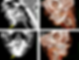
Right eye loss of vision • Xray of the Week What is the the name of the right globe abnormality? Figure 1. Phthisis Bulbi on CT and MR Imaging A. Axial CT scan of the orbits demonstrating the phthisis bulbi with dystrophic calcification (yellow arrow). The globe is small and deformed with enophthalmos. B. Coronal CT scan of the orbits demonstrating the phthisis bulbi with dystrophic calcification (yellow arrow). C and D. Axial MRI T1WI and Axial MRI T2WI of the orbits demonstrating the phthisis bulbi. Note the heterogeneous small, shrunken, calcified, deformed and irregularly shaped right globe, with enophthalmos (green arrow). Figure 2. Phthisis bulbi clinical image in a different patient. Ophthalmic Atlas Image by EyeRounds.org, The University of Iowa is licensed under a Creative Commons Attribution-NonCommercial-NoDerivs 3.0 Unported License. https://webeye.ophth.uiowa.edu/eyeforum/atlas/pages/cataract-phthisis-bulbi-post-cataract-surgery.html Discussion: Phthisis bulbi (PB) is a term given to an anatomically misshapen and atrophied ocular globe, secondary to severe injury or long-standing pathology. PB develops due to persistent inflammation and the eye becomes visibly disfigured and shrunken. Common etiologies of PB include penetrating trauma, radiation, infection, and tumor. After the inciting trauma or pathology, the affected eye undergoes profound inflammatory sequelae including proliferation of fibrosis and scarring. There are three stages leading to the progression of PB: stage I is atrophia bulbi without shrinkage, II is atrophia bulbi with shrinkage, III is atrophia bulbi with shrinkage and disorganization (phthisis bulbi) (1). Patients can be asymptomatic in initial stages or present with a wide spectrum of pain, irritation and blindness. The most common features of PB include a small-sized asymmetrical affected eye with enophthalmos, corneoscleral scarring, hypotonia, and cataracts (Fig.2). End-stage PB can result in retinal detachment. Intraocular exam will demonstrate extremely low intraocular pressure, sometimes reaching 0 mmHg. (2) On CT imaging the globe will be notably shrunken with increased attenuation in the thickened sclera due to diffuse scarring. Possible ossification and foci of dystrophic calcifications can often be seen and it is difficult to assess normal structures of the eye (Fig. 1). MRI will demonstrate various areas of increased signal depending on the degree of calcification in T1-weighted images. T2-weighted images of PB can show filling defects due to calcifications, and FLAIR sequence will exhibit increased signal in the damaged eye contrasting with the contralateral eye (Fig. 1). (3) In the beginning stages of PB, patients can be given a topical steroid and cycloplegic agent to mild symptomatic relief but PB will continue to progress. Currently, the only permanent treatment for PB involves enucleation of the eye when pain becomes severe. Prosthetic rehabilitation of the affected eye has resulted in good cosmetic outcomes especially following enucleation. (1,2) References: 1. Kaiser PK, Friedman NJ, Pineda R. The Massachusetts Eye and Ear Infirmary Illustrated Manual of Ophthalmology. 4th ed. Saunders; 2014. https://bit.ly/2R7bbYG 2. Dohlman CH, D’Amico DJ. Can an Eye in Phthisis Be Rehabilitated? A Case of Improved Vision With 1-Year Follow-up. Archives of ophthalmology. 1999;117(1):123-124. doi:10.1001/archopht.117.1.123 3. Midyett FA, Mukherji SK. Phthisis bulbi. Orbital Imaging; 2015:29-31. doi:10.1016/B978-0-323-34037-3.00017-3 Nirali Dave is a medical student at Medical University of Lublin in Poland, currently doing clinical rotations in New York. Before that she completed her undergraduate education at Rutgers University, and worked as a medical scribe. Nirali was first exposed to basic radiologic imaging while scribing, and was very quickly taken by the field. Her passion for radiology comes from the bridging of anatomy, health technologies, and patient care. In the future, she hopes to complete a diagnostic radiology residency and stay committed to clinical research and patient education. Follow Nirali Dave on Twitter @ndave08 All posts by Nirali Dave Kevin M. Rice, MD is the president of Global Radiology CME Dr. Rice is a radiologist with Renaissance Imaging Medical Associates and is currently the Vice Chief of Staff at Valley Presbyterian Hospital in Los Angeles, California. Dr. Rice has made several media appearances as part of his ongoing commitment to public education. Dr. Rice's passion for state of the art radiology and teaching includes acting as a guest lecturer at UCLA. In 2015, Dr. Rice and Natalie Rice founded Global Radiology CME to provide innovative radiology education at exciting international destinations, with the world's foremost authorities in their field. In 2016, Dr. Rice was nominated and became a semifinalist for a "Minnie" Award for the Most Effective Radiology Educator. Follow Dr. Rice on Twitter @KevinRiceMD All posts by Kevin M. Rice, MD
- Mentoplasty with Submental Silicone Implant
Name the implant and potential complications • Xray of the Week Figure 1. What is the name of this implant? Discussion: Mentoplasty refers to cosmetic chin augmentation that is often used to treat deficient chin projection caused by soft-tissue atrophy and retrusion of the chin (1). Chin retrusion may be further classified as underdevelopment of mandibular symphysis (microgenia) or mandibular retrusion (retrognatia) (2). Augmentation mentoplasty can be performed using various implant materials, autografts, and homografts, and silicone as in this case (1,2). Silicone rubber is preferred over other materials for its resistance to changes in body temperature, calcification, absorption, and degeneration as well as its pliability (2). The silicone implant is typically positioned inferior to the mental foramen in a subperiosteal pocket via an extraoral approach (1,2). Silicone implants are best seen on CT using bone windows, and there is typically variable attenuation with density that is higher than soft tissue but less than bone (1). On MRI, there is very low signal intensity on T1- and T2- weighted sequences (1). Complications include infection, migration, heterotopic bone formation, and foreign body giant cell reaction (1). Mandibular bone erosion is also a common complication and can be evaluated on CT with dental CT software (3). References: Schatz CJ, Ginat DT. Imaging of cosmetic facial implants and grafts. AJNR Am J Neuroradiol. 2013;34(9):1674-1681. doi:10.3174/ajnr.A3214 Vuyk HD. Augmentation mentoplasty with solid silicone. Clin Otolaryngol Allied Sci. 1996;21(2):106-118. doi:10.1111/j.1365-2273.1996.tb01312.x Abrahams JJ, Caceres C. Mandibular erosion from silastic implants: evaluation with a dental CT software program. AJNR Am J Neuroradiol. 1998;19(3):519-522. Amara Ahmed is a medical student at the Florida State University College of Medicine. She serves on the executive board of the American Medical Women’s Association and Humanities and Medicine. She is also an editor of HEAL: Humanism Evolving through Arts and Literature, a creative arts journal at the medical school. Prior to attending medical school, she graduated summa cum laude from the Honors Medical Scholars program at Florida State University where she completed her undergraduate studies in exercise physiology, biology, and chemistry. In her free time, she enjoys reading, writing, and spending time with family and friends. Follow Amara Ahmed on Twitter @Amara_S98 All posts by Amara Ahmed Kevin M. Rice, MD is the president of Global Radiology CME Dr. Rice is a radiologist with Renaissance Imaging Medical Associates and is currently the Vice Chief of Staff at Valley Presbyterian Hospital in Los Angeles, California. Dr. Rice has made several media appearances as part of his ongoing commitment to public education. Dr. Rice's passion for state of the art radiology and teaching includes acting as a guest lecturer at UCLA. In 2015, Dr. Rice and Natalie Rice founded Global Radiology CME to provide innovative radiology education at exciting international destinations, with the world's foremost authorities in their field. In 2016, Dr. Rice was nominated and became a semifinalist for a "Minnie" Award for the Most Effective Radiology Educator. Follow Dr. Rice on Twitter @KevinRiceMD All posts by Kevin M. Rice, MD
- Pulmonary Hamartoma
Lung mass. Diagnosis? • Xray of the Week Figure 1. What is the lung mass? Figure 2. Pulmonary hamartoma Figures 2A and 2B: Axial CT chest demonstrating well-demarcated, solitary peripheral, and inhomogeneous pulmonary mass arising from right lower lung lobe (yellow arrows). Note the low attenuation fat in the mass which is diagnostic of hamartoma. Small calcifications are also present. Figure 2C: Sagittal CT chest demonstrates posteriorly located well-demarcated solitary peripheral pulmonary mass. The mass is above the intact diaphragm (red arrow). Figure 2D: Coronal CT chest and abdomen demonstrates solitary lung mass arising from the right lung superior to the diaphragm with evidence of calcification. The mass is above the intact diaphragm (red arrow). Discussion: A hamartoma is a noncancerous focal proliferation of cells that is typically found in the organ or surrounding structures from which it arises (1). Hamartomas are commonly composed of mesenchymal tissue such as adipose tissue, epithelium, fibrous tissue, and cartilaginous tissue (2,3). Pulmonary hamartomas, dominantly composed of cartilaginous and adipose tissue, are the most common benign lung neoplasm, accounting for approximately 6% of solitary pulmonary nodules (3). They are commonly incidental findings found in the fourth to sixth decades of life with a male predilection and no current identifiable risk factors (3,9). Though often incidentally diagnosed as most patients are asymptomatic, symptoms can present depending on the location of the hamartoma (5). If located within the endobronchial structures, patients can present with cough, hemoptysis, or endobronchial obstruction with associated fever and dyspnea (5). Pulmonary hamartomas are found on diagnostic imaging; however, some cases may require definitive diagnosis with cytological evaluation after biopsy. On imaging, computed tomography (CT) is more sensitive to detecting pulmonary hamartomas compared to chest radiographs (4). Findings on CT demonstrate solitary, well-defined, round or lobulated masses or lobules that are predominantly peripherally located in the lungs (3,4). The size of the mass or nodule can be variable, typically around 2 to 5 cm. However, pulmonary hamartomas can also be larger than 10 cm, as seen in Figure 1 and 2 (8). Approximately 60% of the masses or nodules contain adipose tissue and 30% contain popcorn-like calcifications (6,7). A well-circumscribed solitary pulmonary nodule which contains fat and remains stable in size is virtually pathognomonic of a pulmonary hamartoma (7). If asymptomatic, patients with pulmonary hamartomas do not require treatment. Surgical resection is reserved for rapidly proliferating or symptomatic masses for which malignancy cannot be ruled out (9). Prognosis is typically excellent as hamartomas are commonly slow growing with rare malignant transformation (9). References: Batsakis JG. Pathology consultation. Nomenclature of developmental tumors. Ann Otol Rhinol Laryngol. 1984 Jan-Feb;93(1 Pt 1):98-9. doi: 10.1177/000348948409300122. PMID: 6703601 Leiter Herrán F, Restrepo CS, Alvarez Gómez DI, Suby-Long T, Ocazionez D, Vargas D. Hamartomas from head to toe: an imaging overview. Br J Radiol. 2017;90(1071):20160607. doi:10.1259/bjr.20160607 Singh H, Khanna SK, Chandran V, Jetley RK. PULMONARY HAMARTOMA. Med J Armed Forces India. 1999;55(1):79-80. doi:10.1016/S0377-1237(17)30328-3 Radosavljevic V, Gardijan V, Brajkovic M, Andric Z. Lung hamartoma--diagnosis and treatment. Med Arch. 2012;66(4):281-2. doi: 10.5455/medarh.2012.66.281-282. PMID: 22919888 Thomas JW, Staerkel GA, Whitman GJ. Pulmonary hamartoma. AJR Am J Roentgenol. 1999 Jun;172(6):1643. doi: 10.2214/ajr.172.6.10350308. PMID: 10350308 Chai JL, Patz EF. CT of the lung: patterns of calcification and other high-attenuation abnormalities. AJR Am J Roentgenol. 1994;162 (5): 1063-6 doi:10.2214/ajr.162.5.8165982 Klein JS, Braff S. Imaging evaluation of the solitary pulmonary nodule. Clin. Chest Med. 2008;29 (1): 15-38, v. doi:10.1016/j.ccm.2007.11.007 Siegelman SS, Khouri NF, Scott WW Jr, Leo FP, Hamper UM, Fishman EK, Zerhouni EA. Pulmonary hamartoma: CT findings. Radiology. 1986 Aug;160(2):313-7. doi: 10.1148/radiology.160.2.3726106. PMID: 3726106 Lundeen KS, Raj MS, Rajasurya V, et al. Pulmonary Hamartoma. [Updated 2020 Jul 10]. In: StatPearls [Internet]. Treasure Island (FL): StatPearls Publishing; 2020 Jan. https://www.ncbi.nlm.nih.gov/books/NBK539806/ Rabab Zaidi is an aspiring radiologist and fourth year medical student at the Loyola University Chicago Stritch School of Medicine (SSOM). She currently serves as the Community Support Co-Lead for the Loyola University COVID-19 Response Team and Co-President of the Radiology Interest Group at SSOM. At the Stritch School of Medicine, she has also worked with the Department of Radiation Oncology to study prostate cancer imaging and adaptive radiotherapy techniques, where she learned about the intersection of patient care and radiology. Rabab graduated magna cum laude with a degree in Economics from Loyola University Chicago in 2016. She is further passionate about mentorship, advocacy, and photography. Follow Rabab Zaidi on Twitter @ZaidiRabab All posts by Rabab Zaidi Kevin M. Rice, MD is the president of Global Radiology CME Dr. Rice is a radiologist with Renaissance Imaging Medical Associates and is currently the Vice Chief of Staff at Valley Presbyterian Hospital in Los Angeles, California. Dr. Rice has made several media appearances as part of his ongoing commitment to public education. Dr. Rice's passion for state of the art radiology and teaching includes acting as a guest lecturer at UCLA. In 2015, Dr. Rice and Natalie Rice founded Global Radiology CME to provide innovative radiology education at exciting international destinations, with the world's foremost authorities in their field. In 2016, Dr. Rice was nominated and became a semifinalist for a "Minnie" Award for the Most Effective Radiology Educator. Follow Dr. Rice on Twitter @KevinRiceMD All posts by Kevin M. Rice, MD